
If you’re new to electronics, you may have heard the terms “NPN” and “PNP” regarding transistors.
But what exactly do these terms mean, and what is the difference between NPN and PNP transistors?
In this blog post, we’ll explore the basics of transistors and take a look at the various types of transistors that are available, including bipolar junction transistor (BJT), field effect transistor (FET), unijunction transistor (UJT), Darlington transistor, and insulated-gate bipolar transistor (IGBT).
Besides, we’ll explore the basics of NPN and PNP transistors and discuss their key characteristics, applications, and uses.
We’ll also look at identifying NPN and PNP transistors and provide examples of common circuits that use these types of transistors.
Whether you’re a beginner or an experienced electronics enthusiast, this blog post will provide a solid understanding of PNP and NPN transistors and their role in electronic circuits.
What Is A Transistor, And What Are The Different Types Of Transistors Available On The Market Today?
A transistor is a semiconductor device commonly used to amplify or switch electronic signals.
It is made of a material that is intermediate between a conductor and an insulator. It allows a small current or voltage applied to its input to control a larger current or voltage at its output.
There are several types of transistors available on the market today, including:
1. Bipolar junction transistors (BJTs):
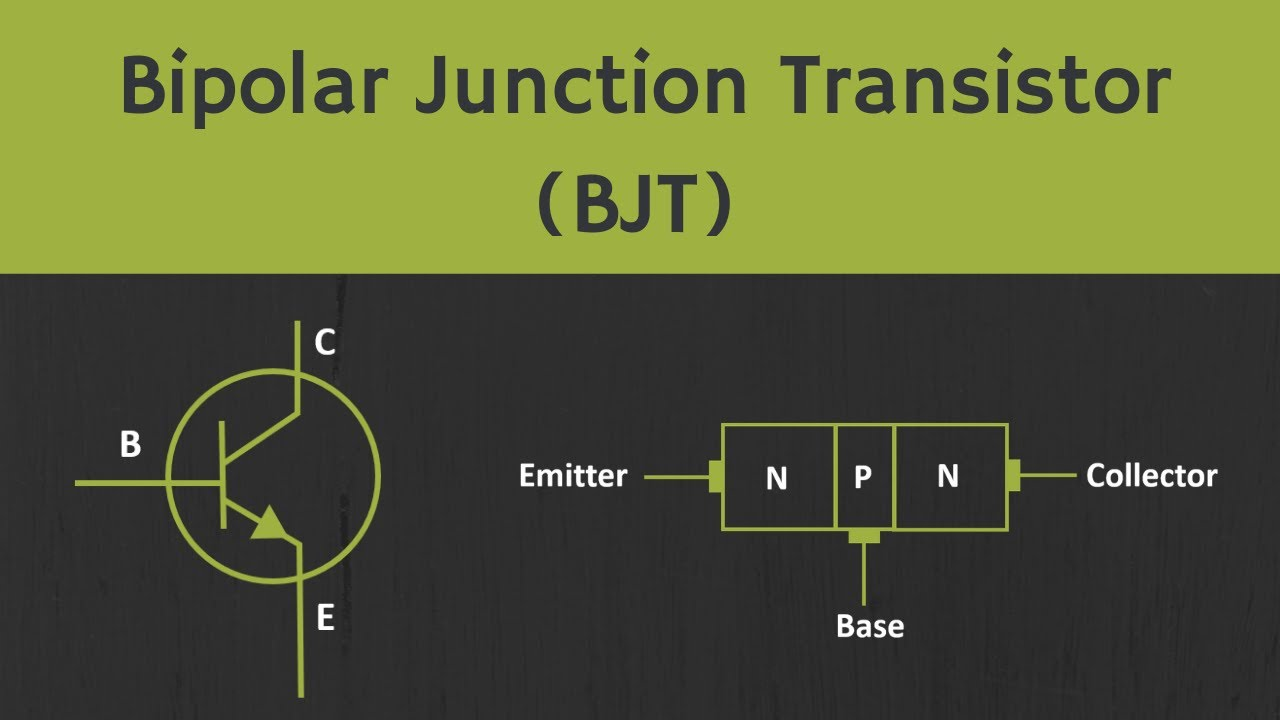
Bipolar junction transistor (BJTs) is a three-terminal semiconductor device with two p-n junctions.
These current controlling devices are made of doped materials, and are called “bipolar” because they use electrons and holes as charge carriers, in contrast to unipolar transistors like field effect transistors (FETs), which only use one charge carrier.
BJTs can be used as amplifiers or switches, depending on their connection.
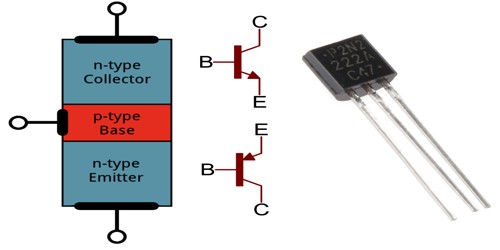
There are two types of BJTs: NPN and PNP.
An NPN transistor has a layer of p-type semiconductor material between two layers of n-type material. In comparison, a PNP transistor has a layer of n-type material between two layers of p-type material. The three terminals of a BJT are the emitter, base, and collector.
o NPN transistor:
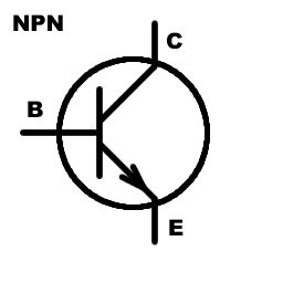
In an NPN transistor, the current flow from the collector to the emitter, as the emitter is made of n-type material and is connected to the negative terminal of the power supply, while the collector is made of n-type material and is connected to the positive terminal of the power supply.
The base terminal of an NPN transistor is made of p-type material and is used to control the flow of current between the emitter and collector.
o PNP transistor:
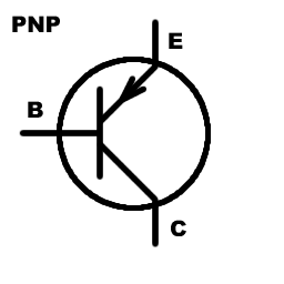
In a PNP transistor, the current flows from the emitter terminals to the collector, as the emitter is made of p-type material layers and is connected to the positive terminal of the power supply, while, the collector is made of p-type material and is connected to the negative terminal of the power supply.
The base terminal of a PNP transistor is made of n-type material and is used to control the flow of current between the emitter and collector base junction.
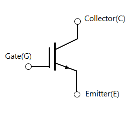
2. Field effect transistors (FETs):
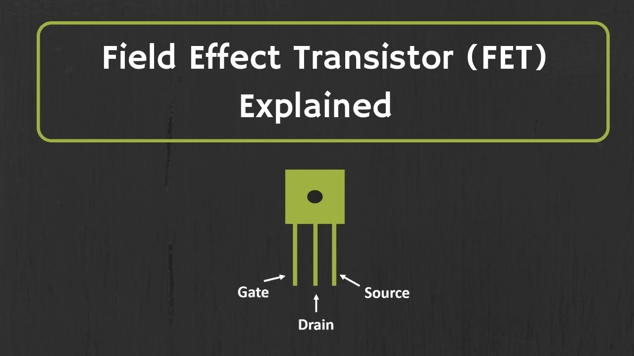
Field effect transistors (FETs) are three-terminal devices that use an electric field to control the flow of current through them.
They are voltage-controlled devices, which means that the voltage applied to the gate terminal controls the current flowing through the transistor. FETs are unipolar devices, which means that they only use one type of charge carrier (either electrons or holes).
There are two types of FETs: n-channel and p-channel. An n-channel FET has a layer of n-type semiconductor material, while a p-channel FET has a layer of p-type semiconductor material.
The three terminals of a FET are the source, gate, and drain.
In an n-channel FET, the source is made of n-type material and is connected to the negative terminal of the power supply, while the drain is made of n-type material and is connected to the positive terminal of the power supply. The gate terminal is made of p-type material and controls the current flow between the source and drain.
In a p-channel FET, the source is made of p-type material and is connected to the positive terminal of the power supply, while the drain is made of p-type material and is connected to the negative terminal of the power supply. The gate terminal is made of n-type material and controls the current flow between the source and drain.
Several types of FETs are available, including metal-oxide-semiconductor field-effect transistors (MOSFETs) and junction field-effect transistors (JFETs). MOSFETs are the most commonly used type of FET, and they are widely used in electronic circuits because of their low power consumption and high switching speeds.
3. Insulated-gate bipolar transistors (IGBTs):
Insulated-gate bipolar transistors (IGBTs) are three-terminal devices that combine the features of metal-oxide-semiconductor field-effect transistors (MOSFETs) and bipolar junction transistors (BJTs).
They are widely used in high-power switching applications because of their high switching speeds, high current carrying capacity, and low on-resistance.
IGBTs can be used as either switches or amplifiers, depending on their connection.
They are typically used in applications with high power levels, such as motor control circuits, inverters, and high-voltage power supplies.
They are also used in high-voltage switching applications, such as switching power converters and high-voltage transmission systems.
Some other types of transistors include:
o Unijunction transistors (UJTs): These are transistors that have three layers of alternating n-type and p-type semiconductor material, and they are used primarily as transistor switches.
o Darlington transistors: These are transistors that are made by connecting two bipolar transistors together and have a high current gain and low saturation voltage.
What Are The Benefits Of Using Transistors In Electronic Circuits?
There are several benefits to using transistors in electronic circuits:
· Amplification: Transistors can amplify small signals, which allows them to be used in a wide range of applications, such as in audio amplifiers, radio transmitters, and receivers.
· Low power consumption: They consume very little power, making them ideal for use in battery-powered devices and circuits where low power consumption is essential, proving to be an ultimate load resistor.
· High switching speeds: They can switch on and off very quickly, which makes them ideal for use in high-speed circuits and switching applications.
· High reliability: Transistors are very reliable and have a long lifespan, which makes them suitable for use in critical applications where reliability is essential.
· Compact size: They are small and lightweight, making them ideal for use in portable electronic devices and circuits where space is limited.
· Low cost: They are inexpensive and widely available, which makes them an economical choice for use in a wide range of electronic circuits.
How Do You Identify An NPN Or PNP Transistor, And What Are Their Uses?
There are several ways to identify whether a transistor is an NPN or PNP transistor:
· Check the transistor’s markings: Most transistors have markings indicating the type of transistor. For example, an NPN transistor may be marked with an “N” or a “-” sign, while a PNP transistor may be marked with a “P” or a “+” sign.
· Measure the transistor’s collector-emitter voltage: In an NPN transistor, the collector-emitter voltage (VCE) will be negative when the transistor is in the “on” state. In a PNP transistor, the collector-emitter voltage will be positive when the transistor is in the “on” state.
· Measure the transistor’s base-emitter voltage: In an NPN transistor, the base-emitter voltage (VBE) will drop below 1 when the transistor is in the “on” state. In a PNP transistor, the base voltage will be positive or will display “OL” (Over Limit) when the transistor is in the “on” state.
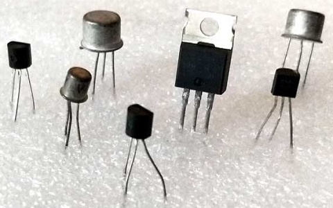
· Check the transistor’s leads: In an NPN transistor, the lead connected to the base is typically the middle lead, while the lead connected to the collector generally is the longest lead. In a PNP transistor, the lead connected to the base is typically the middle lead, while the lead connected to the emitter generally is the most extended lead.
Uses of PNP and NPN transistors:
PNP and NPN transistors are commonly used in various electronic circuits and applications. Some common uses for PNP and NPN transistors include:
· Amplifiers: Transistors are often used as amplifiers in varying position, and both PNP and NPN transistors can be used for this purpose due to its amplifying properties.
· Switches: Transistors can be used as switches to control the flow of current in a circuit. NPN transistors are commonly used in switching circuits where the load is connected to the ground, while PNP transistor works in switching circuits where the load is connected to a positive voltage.
· Inverters: PNP transistors are commonly used in inverter circuits, which are used to invert the polarity of a signal.
· Power supplies: Both PNP and NPN transistors can be used in power supply circuits to regulate current flow managing the balance of positive and negative supply.
· Motor control: These Bipolar Junction Transistors can be used to control the speed and direction of motors, and both PNP and NPN transistors can be used for this purpose.
· Logic gates: Transistors can be used to implement logic gates, which are fundamental building blocks of digital circuits.
· Timers: Transistors can be used in timer circuits, which are used to generate time delays or to measure time intervals, commonly used for computer circuit board.
How Do You Calculate The Current Amplification Factor For A Transistor?
The current amplification factor for a transistor is also known as the transistor’s gain, and it is given by the formula:
α = ΔIC/ ΔIE
Where:
α is the gain
Ic is the collector’s current on collector terminal
Ie is the emitter current
Example:
If the collector current of a transistor is 9 mA and the emitter current is 2 mA, the gain of the transistor would be:
Gain (α) = 9 mA / 2 mA = 4.5 mA
The gain of a transistor is typically expressed in decibels (dB).
To convert the gain from a ratio to dB, you can use the formula:
Gain (dB) = 20 * log10(Gain)
For example, if the gain of a transistor is 10, the gain in dB would be:
Gain (dB) = 20 log10(10) = 20 1 = 20 dB
Note: The gain of a transistor can vary depending on the bias conditions and the frequency of the input signal. In general, the gain of a transistor decreases at high frequencies due to the transistor’s internal capacitances.
What Precautions Should Be Taken When Working With Transistors?
Several precautions should be taken when working with transistors:
· Use appropriate handling and storage techniques: Transistors are sensitive to static electricity, so it is crucial to handle them carefully to avoid damaging them. Transistors should be stored in an anti-static bag or a conductive container when not in use.
· Use appropriate soldering techniques: Transistors should not be soldered using a high-temperature soldering iron, as this can damage the transistor. Instead, a low-temperature soldering iron should be used, and the soldering time should be kept to a minimum to avoid overheating the transistor.
· Observe proper polarity: Some transistors are sensitive to the direction in which they are connected, so it is vital to observe the proper polarity when connecting them to a circuit.
· Use appropriate protective measures: When working with high-voltage circuits, it is crucial to use appropriate protective measures, such as gloves and eye protection, to prevent injury.
· Follow proper circuit design practices: Transistors should be used in circuits that are designed to operate within their ratings. Overloading a transistor can cause it to fail, so it is essential to ensure that it is not subjected to excessive currents or voltages.
· Choose the right type of transistor for the application. There are many different types of transistors, each with its own strengths and weaknesses. If the wrong type of transistor is used, it could damage the circuit or cause it to malfunction.
· Be careful not to exceed the transistor’s maximum voltage and current ratings. Exceeding these ratings can damage the transistor.
Conclusion,
Understanding the transistors, and their types, especially the differences between NPN and PNP transistors, is essential for anyone working with electronic circuits. This knowledge will help you choose the transistor type for your specific application.
