
For more than a century, engineers and scientists have been captivated by the captivating concept of self-induction. It is a fundamental property of electrical circuits that governs the behavior of electromagnetic fields.
Self-inductance is responsible for the fact that a changing current in a circuit induces a voltage across that same circuit. This property has been studied extensively and has led to the development of numerous devices and applications that rely on its principles.
In this blog post, we will delve into the theory of self-inductance, exploring its definition and the factors that influence its value. We will also examine several examples of self-inductance in action, along with some of its most important applications of it.
Whether you are an engineer looking to deepen your understanding of electromagnetic fields or simply curious about the science behind electrical circuit, this post is for you. So let’s dive in!
What Is Self Inductance, And How Can It Be Used?
- Self Inductance Theory – Definition of self-inductance:
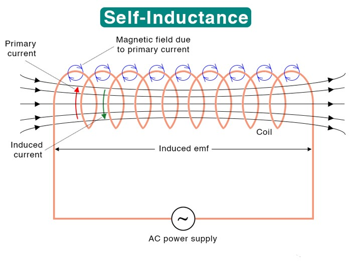
A phenomenon called self inductance occurs when a changing electric current in a circuit induces an electromotive force (EMF) in the same circuit. This self induced EMF always opposes the change in the current that caused it, and it is directly proportional to the current’s rate of change.
The Henry (H) is the unit of self-inductance, which is defined as the level of inductance needed to generate an EMF of one volt when the current alters at a rate of one ampere per second.
Self-inductance is a property of the circuit itself, and it can be influenced by the shape and size of the conductive elements and the materials used to construct the circuit.
The basic self inductance formula is:
VL=−N(dφ/dt)
Where VL is an induced voltage, N is the number of turns within the coil, and dφ/dt is the magnetic flux rate of change within Webers / Second.
- What is Magnetic Flux φ?
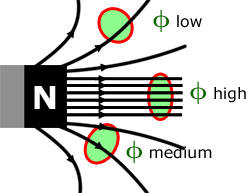
The amount of magnetic field passing through a particular area is measured by magnetic flux. It is a scalar quantity which is defined as the product of the magnetic field strength and the area through which the field lines pass.
Mathematically, magnetic flux can be expressed as:
Φ = BAcos(θ)
Magnetic flux plays a critical role in self-induction as it determines the magnitude of the induced EMF in the circuit. If the magnetic flux through a circuit changes, either due to a change in the magnetic field or the area of the circuit, it will induce an EMF in the circuit that opposes the change in magnetic flux, according to Lenz’s law.
- Explanation of inductors and their role in electrical circuits:
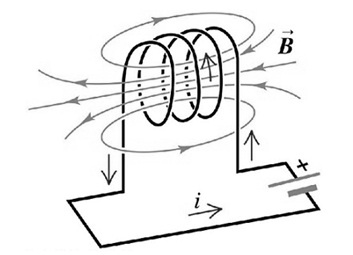
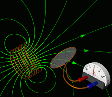
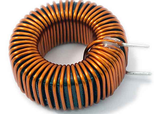
An inductor is a passive electrical component that stores energy in a magnetic field when an electrical current passes through it.
It comprises a coil of conducting wire, typically wound around a core made of a magnetic material.
When an electric current flows through the coil, it creates a magnetic field proportional to the current. As per Faraday’s law, the inductor opposes any changes to the current flowing through it by creating a back EMF proportional to the electric current’s change rate.
Inductors are commonly used in electrical circuits for various purposes, including energy storage, filtering, and signal processing.
They can be used to smooth out variations in current, filter out high-frequency noise, and regulate the voltage of a circuit.
- Understanding how self-inductance is related to mutual inductance:
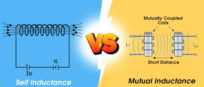
Self-inductance and mutual inductance are related to electromagnetic induction, which occurs when a changing magnetic field induces an electromotive force (EMF) in a nearby conductor.
Mutual inductance is the process of inducing an EMF in a conductor or circuit due to a change in the current flowing through a nearby conductor or circuit.
Self-inductance and mutual inductance are related because they both involve the induction of an EMF in a conductor or circuit due to a change in the current flowing through it.
However, in the case of mutual inductance, the EMF is induced in the nearby conductor or circuit due to the change in the current flowing through the original conductor or circuit.
In other words, In mutual inductance, changes in the current flow in one coil are opposed by the other coil by inducing an EMF in the other coil.
- Self-inductance is not only limited to coil or wire loop
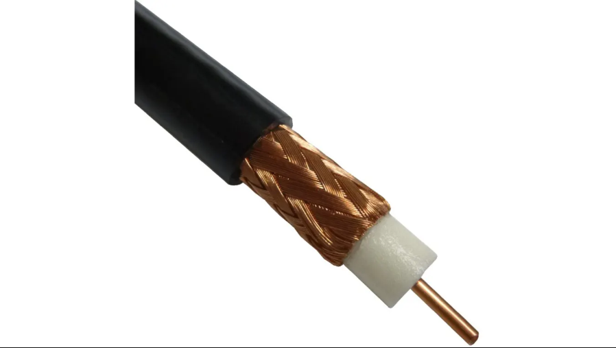
Since self-inductance is a fundamental property of conductors that arises due to the magnetic field generated by an electric current flowing through them, any configuration of conductors, including a long, straight wire, a wire loop, and a coaxial cable, can possess self-inductance.
Coaxial cables are widely used to connect cable modems due to their ability to transmit electrical signals with minimal distortion.
However, the two long cylindrical conductors within the coaxial cable also possess current and self-inductance, which can have adverse effects.
This self-inductance can cause signal degradation, especially at higher frequencies, leading to attenuation and distortion.
To mitigate these issues, coaxial cables are designed with specific geometries and materials that minimize self-inductance and other parasitic effects.
Example of Self-Inductance
Real-world examples of self-inductance in electrical circuits
- Transformers:
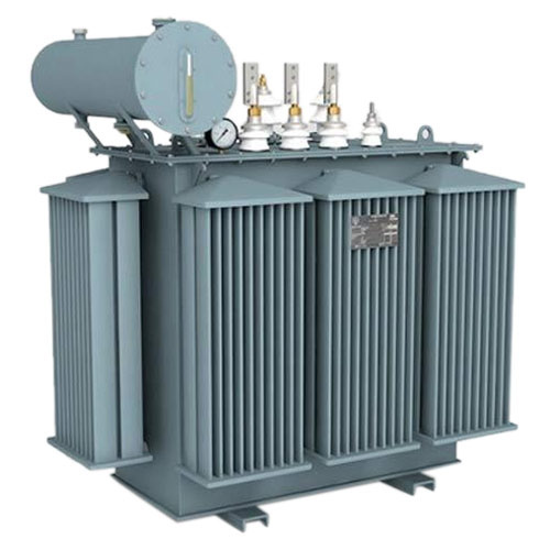
Transformers are a common example of self-inductance in electrical circuits.
A transformer consists of two wire coils, one primary and one secondary. When an alternating (AC) current flows through the primary coil, it creates a magnetic field around it, which induces a voltage in the secondary coil.
This voltage is proportional to the rate of change of the current in the primary coil, and it is the result of the self-inductance of the coils.
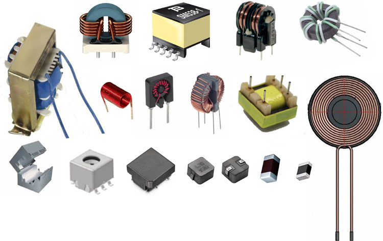
- Inductors:
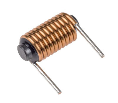
Inductors are components many electronic circuits use to store energy in a magnetic field.
An inductor consists of a coil of wire wrapped around a core made of a magnetic material. When current flows through the coil, it creates a magnetic field, which stores energy.
The magnetic field collapses when the current stops flowing, and the energy is released back into the circuit. This behavior is a result of the self-inductance of the coil.
- Motors:
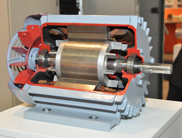
Electric motors use self-inductance to generate a rotating magnetic field.
The rotating magnetic field is produced by changing the direction of the current flowing through the motor’s coils.
This change in direction creates a changing magnetic field, which induces a voltage in the coils.
The induced voltage is proportional to the rate of change of the current in the coils and is the result of the self-inductance of the motor’s coils.
- Inductive sensors:
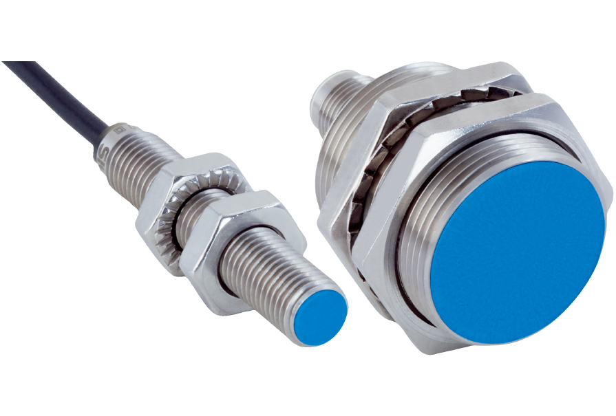
These devices use self-inductance to detect changes in the magnetic field around a conductor. These sensors are commonly used in industrial applications to measure position, speed, and other parameters.
- Switching power supplies:
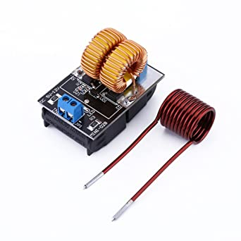
They use self-inductance to store energy and regulate the output voltage. By controlling the self-inductance of the inductor in the power supply, engineers can design a system that is efficient, stable, and reliable.
- Lighting ballasts:
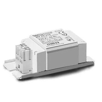
Fluorescent and HID lighting systems use ballasts to regulate the electrical current flowing through the bulbs. Ballasts use self-inductance to limit the current and provide a stable voltage to the bulbs, which improves their performance and extends their lifespan.
- Radio and television broadcasting:
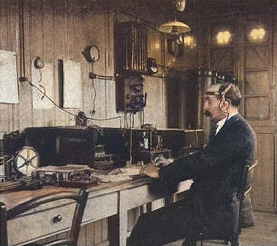
In radio and television broadcasting, self-inductance is used to create tuned circuits that can select specific frequencies for transmission or reception.
Calculation of self-inductance in an example circuit
The self-inductance of a coil can also be calculated using the formula:
L = (μ0 n^2 A)/ l
where L is the self-inductance of the coil, μ0 is the permeability of free space, n is the number of turns in the coil, A is the cross-sectional area of the coil, and l is the length of the coil.
Let’s use this formula to calculate the self-inductance of a coil with the following dimensions: n = 100 turns, A = 0.01 m^2, and l = 0.1 m.
First, we need to find the value of μ0, which is a constant equal to 4π × 10^-7 H/m. Substituting the values given into the formula, we get:
L = (4π × 10^-7 H/m) (100^2 turns^2) (0.01 m^2) / 0.1 m
Simplifying this expression, we get:
L = 0.0126 H
So the self-inductance of the coil is 0.0126 Henry.
Factors Affecting Self-Inductance
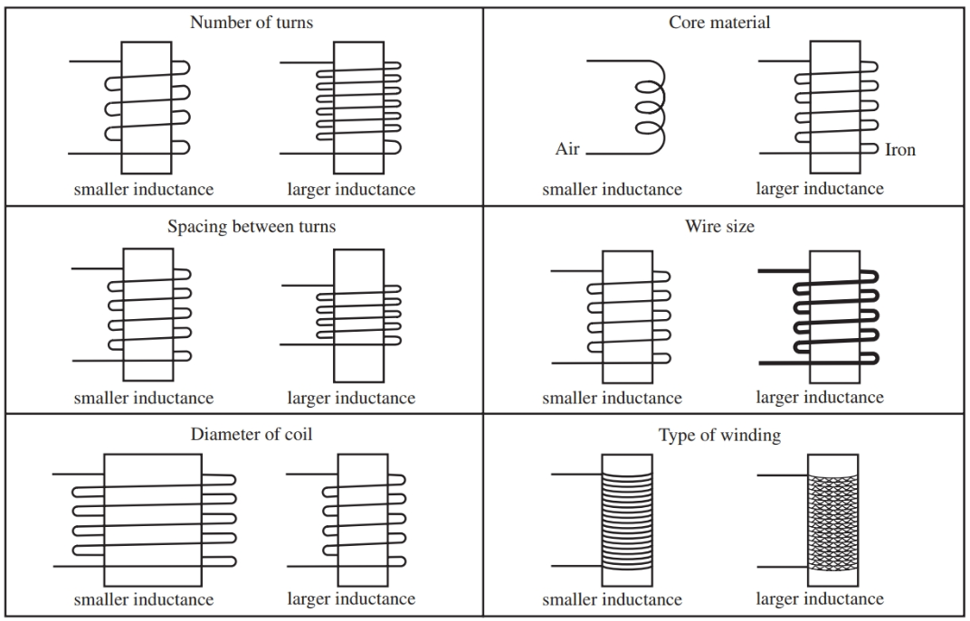
- The number of turns in the coil:
The self-inductance of a coil increases with the number of turns in the coil. This is because the magnetic field produced by each turn of the coil adds up to create a stronger overall magnetic field.
- The shape and size of the coil:
The shape of the coil can also affect its self-inductance. For example, a solenoid with a relatively long coil and, thin shape will have a higher self-inductance than a coil with a shorter, wider shape.
- The presence of magnetic materials:
The presence of magnetic materials can also have a significant effect on the self-inductance of a coil. When a magnetic material is placed inside the coil, it can change the strength and distribution of the magnetic field, affecting the self-inductance of the coil.
The effect of magnetic materials on self-inductance depends on the material’s permeability. Permeability is a measure of a material’s ability to conduct magnetic flux. It can be either higher or lower than the permeability of air or vacuum, often used as reference materials.
Materials with high permeability, such as iron, nickel, or cobalt, can concentrate the magnetic field within the coil, leading to an increase in self-inductance. This is because the magnetic field lines passing through the coil are more tightly confined by the high-permeability material, increasing the total magnetic flux made through the coil.
On the other hand, materials with low permeability, such as aluminum or copper, have little effect on the magnetic field within the coil, resulting in little change to the self-inductance of the coil.
- The frequency of the current:
The self-inductance of a coil can also be affected by the frequency of the current flowing through it. At higher frequencies, the self-inductance of a coil may decrease due to the skin effect, which causes the current to flow mainly near the conductor’s surface rather than through its entire cross-section.
- The area of the coil:
The self-inductance of a coil also depends on the area of the coil. A coil with a larger cross-sectional area will have a larger self-inductance than a smaller one.
- The current through the coil:
A coil’s self-inductance also depends on the current flowing through it. As the current increases, the magnetic field produced by the coil becomes stronger, leading to a rise in self-inductance.
Self-Inductance of a Solenoid
A solenoid is a coil of wire wound in a cylindrical shape with a uniform diameter and spacing between the turns. It is one of the most common geometries in electromagnetics due to its simplicity and versatility.
When an electric current flows through a solenoid, it generates a magnetic field within and around it. This magnetic field induces an electromotive force (EMF) in the solenoid itself, known as self-induction.
- How to calculate the self-inductance of a solenoid?
Calculation of the self-inductance of a solenoid is based on the geometrical and physical properties of the solenoid. The self-inductance of a solenoid can be calculated using the following formula:
L = (μ0 n^2 A)/ l
Where,
- L is the self-inductance in henries
- μ is the permeability of the core material
- n is the number of turns per unit length of the solenoid
- A is the cross-sectional area of the solenoid
- l is the length of the solenoid
The formula shows that the self-inductance of a solenoid is directly proportional to the number of turns per unit length, the cross-sectional area, and the length of the solenoid.
Note: If the core is made up of a magnetic material of permeability μ, then you can use the formula:
L = (μN2A) /l
- The effects of solenoid geometry on self-inductance:
Understanding the effects of solenoid geometry on self-inductance is crucial in designing electromagnetic devices.
For instance, increasing the number of turns per unit length, the cross-sectional area, or the solenoid’s length will increase the solenoid’s self-inductance. Additionally, the presence of a core material with high permeability will also increase the self-inductance of the solenoid.
The geometry of the solenoid also affects the uniformity of the magnetic field within the solenoid, which in turn affects the self-inductance.
The magnetic field inside a solenoid is nearly uniform along its axis, but it varies significantly in the radial direction.
This non-uniformity of the magnetic field can be minimized by using a high aspect ratio, which is the length ratio to the solenoid’s diameter. A high aspect ratio solenoid will have a more uniform magnetic field and hence a more uniform self-inductance.
Mutual Inductance
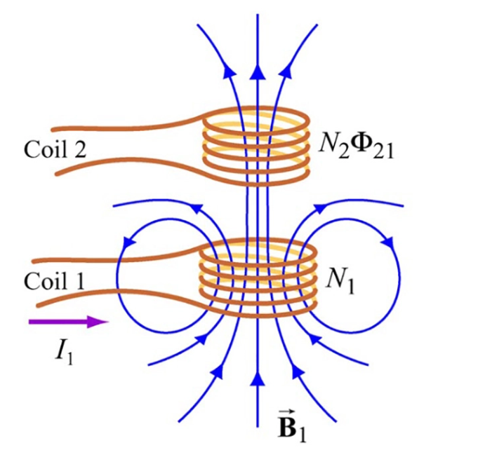
Mutual inductance is a fundamental concept in the study of electromagnetism. It refers to the ability of two circuits to influence each other’s magnetic field and generate an induced voltage.
When two coils are placed close together, and an alternating current is passed through one of them, it creates a changing magnetic field around it. This changing magnetic field then induces a voltage in the second coil, causing a current to flow through it.
This phenomenon is known as mutual inductance.
The unit of mutual inductance is the henry (H), which is the same as the unit of self-inductance.
Mutual inductance is closely related to self-inductance, as both are caused by the magnetic field produced by the changing current flowing through a coil. However, while self-inductance measures the magnetic field produced by a coil on itself, mutual inductance measures the magnetic field produced by one coil on another coil.
- Calculation of mutual inductance:
There are several formulas for calculating mutual inductance between two coils, but the most standard formula is:
M = μ₀ μr N₁ N₂ * A / ℓ
Where:
- M is the mutual inductance between the two coils, measured in henries (H).
- μ is the permeability of free space. It is approximately 4π x 10^-7 H/m.
- N₁ and N₂ are the numbers of turns in the two coils.
- A is the cross-sectional area of the two coils, measured in square meters (m²).
- ℓ is the distance between the two coils, measured in meters (m).
This formula assumes that the two coils are perfect solenoids, meaning they have a uniform magnetic field and no magnetic flux leakage. If the coils have non-uniform magnetic fields or significant flux leakage, the formula may need to be modified, or a more complex formula may be necessary.
Rectangular toroid mutual inductance
In a rectangular toroid, mutual inductance occurs when two coils are wrapped around the toroid so that they are close to each other.
The rectangular toroid is a toroidal (doughnut-shaped) core with a rectangular cross-section made of a magnetic material such as iron or ferrite.
Two coils, the primary coil, and the secondary coil, are wound around the toroid in such a way that they are near each other. The primary coil is connected to a power source, generating an alternating current (AC). The AC current flows through the primary coil, creating a magnetic field around it.
The primary coil’s magnetic field cuts through the secondary coil’s turns, inducing an EMF in it.
The magnitude of the EMF induced depends on the rate of change of the magnetic field, the number of turns in the secondary coil, and the mutual inductance between the two coils.
Whereas the mutual inductance depends on the geometry of the toroid, the distance between the two coils, and the number of turns in each coil.
Limitations of Inductors
Inductors are an essential component in many electrical circuits, but they have limitations, such as:
- Saturation:
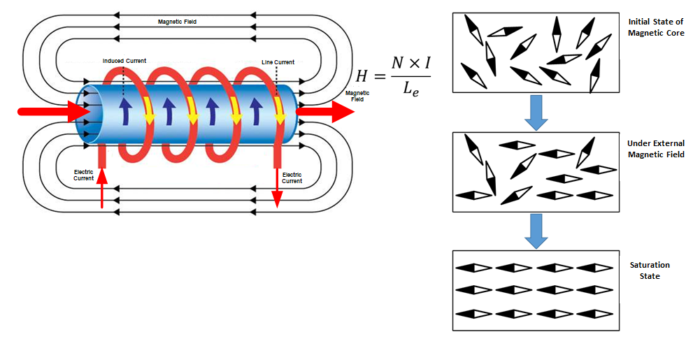
When the magnetic field created by an inductor becomes too strong, the inductor can become saturated. When an inductor is saturated, it no longer behaves like an inductor, and it can lead to a significant change in the circuit’s behavior.
Saturation can occur when an inductor is exposed to high levels of current, which can cause the magnetic field to become too strong.
Designers may need to consider using an inductor with a higher saturation current rating or multiple inductors in parallel to distribute the current and reduce the risk of saturation.
- Parasitic capacitance:
Inductors have parasitic capacitance, which can limit their performance in certain circuits.
Parasitic capacitance results from the physical properties of the inductor, and it can lead to unwanted effects, including resonance and oscillation.
Designers may need to use capacitors to compensate for the parasitic capacitance of inductors or consider using a different type of inductor with a lower parasitic capacitance.
- Eddy currents:
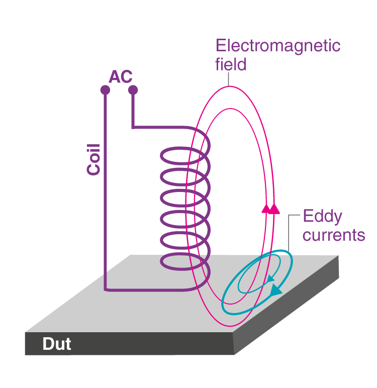
Eddy currents can limit the performance of inductors in high-frequency applications. Eddy currents flow in the inductor’s core, which can cause the core to heat up and reduce the inductor’s efficiency.
Designers have several options for compensating for eddy currents in inductors. By carefully considering the materials and design of the inductor, designers can improve the efficiency and performance of the inductor and reduce the impact of eddy currents on the circuit.
- Size and weight:
Inductors can be large and heavy compared to other circuit components, which can limit their use in certain applications where space and weight are at a premium. This can also limit the ability to integrate inductors into certain devices or systems.
Designers may need to consider using alternative components or redesigning the circuit to reduce the size and weight of the inductor.
- Frequency limitations:
Inductors have a limited frequency range where they are effective. The inductor’s impedance can become too high at high frequencies, making it less effective or useless. This limitation can restrict the use of inductors in high-frequency applications.
Designers may need to consider using alternative components, such as capacitors or resistors, in these applications.
- Temperature sensitivity:
Inductors can be sensitive to temperature changes, which can cause changes in their performance. As the temperature of the inductor changes, its inductance can change, which can affect the circuit’s behavior.
This limitation can be especially important in high-temperature applications, where the inductor may need to be designed to withstand high temperatures.
Designers may need to use materials that can withstand high temperatures or consider using alternative components that are less sensitive to temperature changes.
- Magnetic interference:
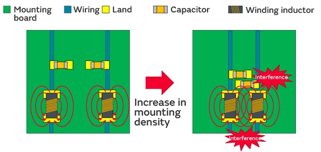
Inductors can produce magnetic fields that can interfere with other components in the circuit. This interference can lead to unwanted noise, signal distortion, or malfunction.
In some cases, magnetic shielding may be necessary to reduce the effects of the magnetic fields produced by inductors.
Designers may also need to use alternative components that produce less magnetic interference or redesign the circuit to reduce the impact of the interference.
Problem-Solving Strategy: Self-Inductance
Calculating self-inductance in a circuit can be complex, but a step-by-step problem-solving strategy can help make the process more manageable.
Here is a step-by-step guide to calculating self-inductance in a circuit:
- Identify the circuit elements: Start by identifying all the components in the circuit, including any inductors, capacitors, resistors, and voltage or current sources.
- Isolate the inductor: If the circuit has multiple inductors, isolate the inductor whose self-inductance you want to calculate.
- Determine the current flow: Determine the direction and magnitude of the current flowing through the inductor.
- Calculate the magnetic flux: Use Faraday’s law to calculate the magnetic flux through the inductor.The equation is:EMF = -L dI/dtWhere EMF is the electromotive force, L is the self-inductance of the inductor, and dI/dt is the rate of change of current through the inductor.You can also use the following alternative equations:VL = −N (dϕ / dt)Where VL is the induced voltage in volts, N is the number of turns in the coil and dφ / dt is the rate of change of magnetic flux in webers / second.Or,VL = −L (di / dt)Where VL is the induced voltage in volts, and dI/dt is the rate of change of current through the inductor.
- Simplify the equation: If possible, simplify the equation by assuming that the current through the inductor is constant or that the inductor has negligible resistance.
- Solve for self-inductance: After simplifying the equation, solve for the inductor’s self-inductance. Rearrange the equation to isolate L and plug in the values of EMF and dI/dt that you calculated in step 4.
- Check your answer: Double-check your calculations to ensure you have the correct value for self-inductance. You can do this by comparing your result with the expected value based on the physical properties of the inductor.
- Repeat for other inductors: If multiple inductors exist in the circuit, repeat steps 2-8 for each inductor to determine its self-inductance.
- Reassemble the circuit: Once you have calculated the self-inductance of each inductor, reassemble the circuit and use the values to analyze the circuit’s behavior.For example, you can use self-inductance to calculate the circuit’s time constant or determine the circuit’s response to changes in current or voltage.
Conclusion
Self-inductance and mutual inductance are important concepts in electrical engineering that describe a conductor’s ability to generate an electromotive force (EMF) in response to a change in the current flowing through it.
By understanding the theory behind self-inductance and mutual inductance, including the factors that affect them and the methods used to calculate them, we can gain valuable insights into the behavior of electrical circuits and devices.
Besides, our outlined step-by-step problem-solving strategy can help you calculate self-inductance in a circuit. By following these guidelines, you can approach the task of calculating self-inductance with confidence and arrive at accurate results.
Overall, self-inductance is a fundamental electrical engineering concept with many practical applications. By understanding what self-inductance is and how it can be used, we can design and optimize electrical systems that are efficient, reliable, and effective.
