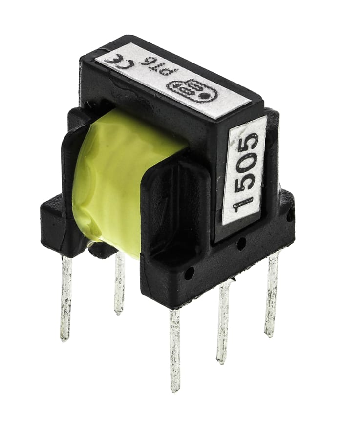
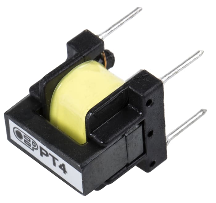
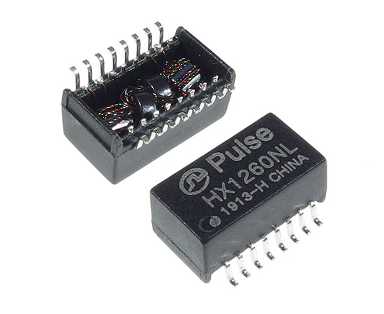
Pulse transformers are used widely in many industries; it is used to distribute power and also can hold vast loads of power and signals. If you consider an example of vacuum devices, you will observe that these usually work with high-power pulse voltage, which high-power pulse transformers can create.
These transformers usually have a compact structure and offer excellent repeatability. In most applications where these transformers are used, they cater to the wide pulse width, high energy efficiency, and low rise time.
These transformers, when compared to a similar type of transmitters, are better because they can transmit a tremendous amount of power and also can have a high frequency.
This article below comprises a detailed guide that will help you in understanding the basics of pulse transformers and their uses in technology, so let’s read through below.
Purpose and Importance of Pulse Transformer
A basic transformer is upgraded to create pulse transformers and establishes electrical pulses with high velocity and stable amplitude. Pulse transformers are used to transmit digital data for transmission or in transistors, and it is suitable for use as gate drive circuits.
An ideal transformer must-have features like distributed capacitance followed by galvanic isolation. The capacitance must have minimal coupling that ensures the safety of the circuit.
The pulse transformers can handle multiple signals, it is also suitable for complimenting the logic drives, and this is also applicable to offer ease in transmission lines. These pulse transformers can operate at lower power level, and some are used as wide-band transformers.

Digital networks also use these transformers to reduce signal distortions, and many other properties like inter-winding capacitance, individual winding capacitance, inter-winding, and individual winding resistance can be used. It helps in the assessment of the frequency range and conformance of signals.
Many things, like inductance, operating frequency response, voltage ratings, power grades, winding configurations, etc., influence the pulse transformers’ design.
A pulse transformer will use two things, either power or signals. Whether it is power or signals, they both have their place and high open-circuit inductance followed by a minimal tolerance for the dispersed capacitance and leakage inductance.
Many applications of pulse transformers make them popular in many devices, especially the ones used in the transmission of data and communication systems.
Working of Pulse Transformer
A typical pulse transformer operates to change the direction of the electric power from AC to DC, and they are specifically used in industrial applications to cater to this purpose.
Electromagnetic induction is used to operate pulse transformers, and an electromagnetic field is created in which the current is carried through a coil of wire. Due to the generation of this field, a voltage is generated in the coil present nearby with a wire.
The working principle of a pulse transformer is discussed in detail below:
Basic Principle of Operation
A switching device turns on or off the power in a pulse transformer. A switching device is used at an operating frequency and pulse duration that provides the power needed.
This helps control the temperature and transformer simultaneously, providing electrical isolation between the input and output signal. The pulse transformers are power-type pulse transformers in a forward converter power supply. High-power pulse transformers even exist that have a power capacity of 500 kilowatts.

Magnetic Coupling
In a magnetic coupling, the energy is transferred from one circuit to another, which is not connected through any physical connection but is linked through a magnetic flux. Mutual inductance is created through the common magnetic flux that links the coil.
This magnetic action is based on Faraday’s law of electromagnetic induction, which states that the electromotive force is created in a closed circuit when the magnetic flux linked with the circuit has changed.
In other words, the induced electromotive force is opposite to the change of flux and is equal to the change in flux leakage inductance rate.
When a flux is created between the links of inductors, the inductors are said to be coupled magnetically. The amount of inductance between the number of windings determines the frequency response curve’s shape.
Voltage and Current Ratio
The voltage-to-current ratio is another essential factor that needs to be catered to in the working of pulse transformers. The voltage ratio of 1:5 shows that for every one volt on the primary, 5 volts will be there on the secondary winding. In a transformer where the secondary voltage exceeds the primary one, the transformer is said to be a step-up transformer.
The transformers are designed in a way that the design focuses on ensuring the output signal has been delivered successfully. However, the turn ratio of this transformation can help adjust the signal’s amplitude and provide a matching impedance between the load and source.
Pulse transformers are used mostly for transmitting digital data and gate driver security of transistors. Various signal pulse transformers are also known as wide-band transformers for digital networks and communication systems.
Types of Pulse Transformers
There are many kinds of different pulse transformers, each with its own purposes and functions used in multiple applications. Some of these types of transformers are discussed below:
Single Ended Pulse Transformer
Single-ended pulse transformers are power transformers that use a single phase of alternating current and rely on a voltage cycle that is operational in a unified time phase.
Such transformers are used to step down a long distance and currents of localized transmissions at a power level suitable for commercial and resistance applications with a lighter setup.
In this kind of power transformer, the change in current is identified in the ratio of primary to the secondary winding. If these transformers have a ratio of 1:1, they are suitable for using them as an isolation barrier in circuits.
A single-end pulse transformer is used for commercial or residential voltage droop applications and power distribution. They are also used in multiple applications, and in such cases, the lower voltage level output is rectified in DC before the appliances are powered, for instance, in computing devices.

Push-Pull Pulse Transformer
One of the pulse transformer designs comprises the push-pull pulse transformer. This transformer has the capability to reverse the current by turning the switches of the transformers on and off.
These transformers provide a steady input current, and in the input pulse, it also reduces the noise; hence it proves to be a perfect choice for use in applications that need high power.
Forward Converter Pulse Transformer
Forward converter pulse transformers are DC/DC converters that either increase or decrease the output voltage level. These transformers are also known for providing galvanic isolation for managing the load.
In case of output windings being multiple in quantity, they can provide higher and lower voltage outputs at the same time.
Flyback Converter Pulse Transformer
A flyback transformer is a device that is used for energy conversion, and it carries out the function of sending energy from one end of the circuit to another end at a constant level of power. This transformer is also known as a line output transformer as it transmits the output voltage to the rest of the half portion of a circuit.
It is a step-up transformer because it has a huge power level voltages to offer high voltage capacity.
Half Bridge Pulse Transformer
Half bridge pulse transformers are used as DC-DC converters and supply output signal at a higher or lower level than the input signal. These transformers can also offer electronic isolation. These transformers can yield high voltage output power and have parts with a size that is smaller and less expensive.
Full Bridge Pulse Transformer
A full bridge transformer is used to ensure dc isolation, and at the same time, it also offers the stepping up and down of the input voltage. This transformer is also used to provide several output voltages at the same time and is used for reversing the polarity.
A gate drive transformer offers zero line voltage switching, sharing single primary winding.
Design Considerations for Pulse Transformer
The design of pulse transformers is different in terms of inductance, size, bandwidth, voltage droop, operating frequency, winding capacitance, and many other parameters.
However, it is always an approach of designers to ensure that parasitic elements like leakage inductance and winding capacitance have been minimized. It is done by way of using multiple winding configurations that help in the optimization of coupling that is present between the windings.
Core Material Selection
Material selection plays a very important role in pulse transformers as they have a significant role to play. The material must be perfect, and everything must be considered when choosing a material, like saturation flux density, ensuring appropriate pulse shape, heating element, etc.
Designing a pulse transformer with low leakage inductance and low losses of core requires materials with high flux density; the magnetic core may comprise materials like amorphous alloys, ferrite, and silicon steel.
The amorphous cores comprise flux swing, which is larger, and also it has lower core losses; this material allows to have transformers designed with energy efficiency, compact structure, and impedance matching.
On the other hand, the magnetic core can also be used, which plays a significant role as it offers distributed capacitance and decreases core loss.
Wire Size and Turns Ratio
In a typical pulse transformer, the wire size and turns ratio is 1:1. However, depending on whether the pulse amplitude is a peak pulse amplitude or low-power pulse transformers, the ratio can be adjusted.
Primary and Secondary Inductances
The pulse-forming network in a pulse transformer will comprise a primary driving circuit with the primary winding powered by a source. However, the secondary driven circuit has secondary winding comprising the coil connected with the load.
The number of windings plays an essential role in assessing the voltage in a transformer, and the primary circuit can offer a high voltage with high frequencies or low voltage. It depends on whether the transformer is a step-up or step-down transformer.
Core Saturation
The core saturation in the pulse transformer is undesirable because it releases a leakage field in the form of magnetic flux, which could cause the inductance of current in the circuits to present nearby. It could cause bursts of high frequencies that interfere with the radio frequency.
Magnetic saturation can also be caused when the primary voltage has been excessive, or the transformer is operated at a lower frequency. It also happens if any of the winding has a DC. It must be prevented by limiting current during high load times.
Leakage Inductance
Leakage inductance causes power transfer in a transformer to be impacted. It may also cause the voltage to spike across the switches and leads to damaging them. To deal with this issue, a snubber can be implemented to help reduce voltage spikes.
The leakage inductance also causes an indication of the coupling efficiency between primary and secondary windings. Hence these coils must be placed as close as possible to these pulse signal transformers to reduce the magnetic field and the negative impact of parasitic elements.

Applications of Pulse Transformer
Switching Power Supplies
In switching power supplies a pulse transformer can be used and has its primary winding and secondary winding concentrically wounded having a common core. It also has electrostatic shielded foils interposed in between these windings, followed by an insulator despised in the foils.
High Voltage Pulse Generators
High-voltage pulse generators comprise power transformers to boost voltage. For instance, in microwave tube circuits, the role of these pulse transformers is quite essential, and they will manage the power rating.
Power Inverters
In power inverters, the pulse transformers generate power because of their high pulse amplitude and galvanic isolation. It helps amplify the AC voltage from a battery or a generator acting as a source to the highest peak voltage value.
Audio Transformers
Audio transformers are used to carry the audio power and boost this, and pulse transformers are a suitable choice as they can carry pulses with an excellent fidelity level. Hence, pulse transformers are widely used with audio transformers.

Advantages and Disadvantages of Pulse Transformer
A pulse transformer is no doubt used in multiple applications but along with advantages, it has various disadvantages as well.
Advantages
- It is smaller in size and has a compact structure.
- It offers high frequencies and high isolation voltage.
- It doesn’t need any external power
- It can transmit high energy.
- It comprises multiple windings
- It provides control and insulation.

Disadvantages
- When these transformers are used at low frequencies, the output wave-forms differ from each other.
- In the primary winding, the DC supply leads to cause a decrease in the saturation of the core.
- It has the tendency to saturate at lower frequencies. Hence it is capable of being used with maximum frequencies only.
- Due to magnetic coupling, the signal needs to be clarified.
Conclusion
The guide above features every detail about pulse transformers and you must have got an idea of the details that you might be looking forward to after going through it.
Taking notes from this guide, you cannot make the best use of this transformer in your applications. If you have any comments to share, you can do so in the comment box below.

