
There are different electronic components used in circuits of multiple electronics, and along with them, an inductor is also a commonly used component. It is a passive component with two terminals and comprises a wire coil.
The inductor is more or less the same as the resistor in terms of look and has a coil length wired up. The purpose of an inductor is to store energy in the magnetic field as soon as the electric current flow through it.
Inductors are widely used in many electronic devices and also play a significant role. If you look forward to gaining more knowledge about inductors, follow the guide below.
It is a comprehensive guide to inductors and how they work, different types of inductors, the details on coils used within them when used with many devices, and how they react with other components. It has many circuit applications, and a detail of everything is discussed below, so let’s read through it below.
Basic Principles of Inductor Coils
In electrical circuits, inductors play an important role in leading the devices to work efficiently, which is essential to the circuits.
What is the Function of an Inductor?
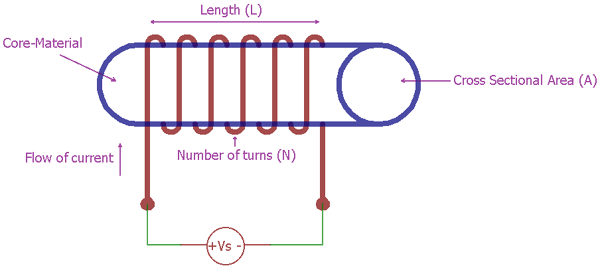
The inductor comprises insulated wire which is wounded into a coil length. It contains a core material designed to get the most benefit out of the electricity and magnetism since it helps create a magnetic field when current flows through it.
They carry out many purposes, like blocking, chocking, or attenuating the noise in circuits. At the same time, it also filters circuits to store and transfer energy in power converters.
They are based on the type of core they have, the inner core through which they are wound; for instance, there are hollow core inductors, also called free air core inductors, ferrite core inductors, iron core inductors, etc.
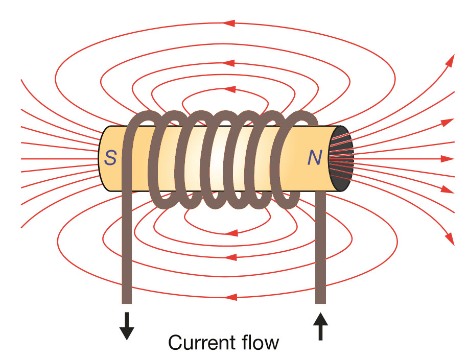
What are the Magnetic Fields and Magnetic Flux in the Inductor?
The electric current flows through the inductor, the magnetic flux generated here is directly proportional to the electric current. The role of the inductor is to oppose the rate of change of current flowing through the circuit, and it’s because of the energy created in the magnetic field due to being self-induced.
In electronic devices, the inductor will oppose the changes in current. However, the flow of DC current passes steadily through the circuit. This ability of the inductor to oppose the current changes is related to the magnetic flux linkage.
Significance of Inductor in Circuits
Inductors are present in almost all electronic circuits as they have a significant role to play as you can see, in power supplies, they prevent sudden current changes, and hence in power supplies, it controls the output current and voltage.
Different Types of Inductors
An inductor is based on different kinds of core material; depending on that, there are types of inductors with their applications. The common inductors are described below based on other inductor cores:
Iron Core Inductors
Iron is such material known for its magnetic permeability, and hence it is used in the making of inductors. When iron is used in an inductor, it takes the form of an iron core, and these are suitable for use in low-frequency line filtering because they have a greater inductance.
The iron core inductor is mainly used in audio equipment and power conditioning as they are also known as power inductors, industrial power supplies, and other low-frequency applications.
The iron core inductor has low core losses and is very simple to work with. It also has many sizes and low spatial requirements, followed by accessible enclosure alternatives.
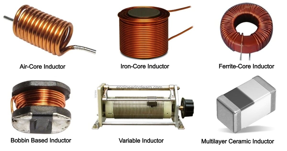
Air Core Inductor
An air core inductor is an inductor with no core; instead, its core is open air. Due to the lower permeability, the air core inductors have low inductance. The current rate rise is very fast for a given voltage in them, making them suitable for high frequencies in applications like RF circuits, snubber circuits, pi filters, radio, and TV receivers.
The air core inductors are free from saturation, and they do not even have any iron losses having lower distortion too, as needed by high-frequency applications.
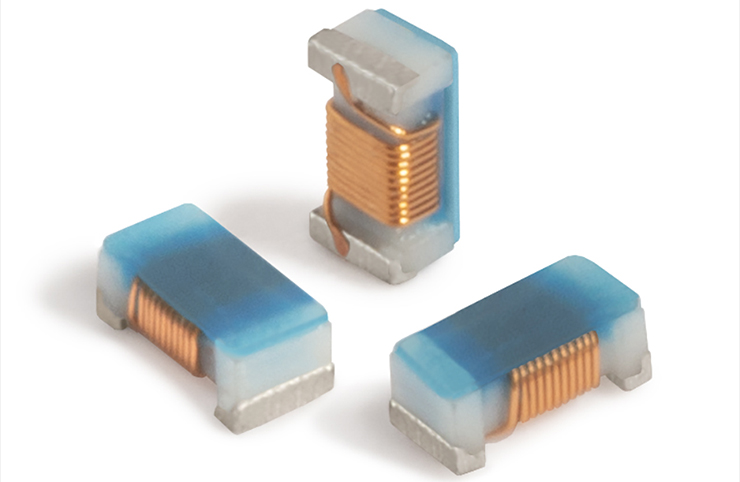
Ferrite Core Inductor
Ferrite core inductors comprise ferrite, a material made by mixing iron oxide with metals like zinc and nickel. It forms a ceramic material. In inductors, ferrite powder is used, combined with epoxy resin, and a core is formed as a mold around which a magnetic wire has been wounded.
The ferrite core inductors offer a performance that is quite improved compared to other inductors and provides high permeability to the coil area. It offers a high magnetic field and also a high inductance.
They are used in many applications which operate at high frequencies, like power conversions, interference suspension, broadband, etc.

Inductor Design
Every type of inductor has a particular application; hence, according to that, the design procedure is also different. The first thing in designing an inductor is the core material selection, then comes the winding, which is a wire type used, and these must comply with certain inductance specifications and current ratings.
Inductor Design Process
Let’s consider the creation of a DC current inductor used in DC/DC converters, and it has a critical function there. The main difference between other inductors and DC inductors is that in a DC inductor, the DC is dominant compared to the AC current.
The first step to designing this kind of inductor requires assessing the core material chosen; in the DC current inductors, the ferrite core is one of the highly opted core materials. The ferrite offers a better permeability, operating range for frequency and temperature, and magnetic field flux saturation limit.
Once the core material is selected, the process of choosing the method starts. Different ways may be selected for the design process, and however, the three common ones are:
- Area Product Method
It is the most common method where the energy stored is calculated along with the maximum magnetic fields, frequency, and current density present through the winding of the coil area.
The AP value has been assigned in every core shape, which helps in the calculation. You can select a core with a greater AP value and ensure that the chosen material has the saturation limit established at the start.
This value considers the window space to the winding and is represented by the K factor for every type of converter. It is very popularly used in the design of transformers because of the inconsiderable gap.
- Losses Method
You are aware of the maximum loss the converter would have for target efficiency, and hence it allows you to estimate the losses in the magnetic field; this way, you can choose the components that offer these losses.
After you have chosen the core losses and winding, you can easily calculate the loss of your core candidates for the various number of turns. The most significant advantage this method offers is the maximum temperature rise, as the design can easily be started at that point.
- The Energy Method
The best option chosen for the inductor design is the energy method, and the energy is calculated as needed. It requires understanding the energy the inductor stores and ensuring that the gap has sufficient space to store energy and can be calculated easily.
The voltage across the inductor can be calculated using the mathematical formula v= L (di/dt). The voltage drop across the inductor and the rate of change of current flowing are directly proportional.
The application of the inductors will help determine the inductor size; in power circuits, for instance, larger inductors are needed. In RF applications, the RF tuning coils are present, which need ferrite core inductors.
The RF devices have a lower power requirement; hence, the inductors require shielded components so that the magnetic coupling between the components can be reduced.
Similarly, the power factor corrections tend to adjust the power factor in alternating current power circuits close to unity, and this is done by adding a load in the opposite direction and equal to the circuit so that the impact of the load reaction is canceled.
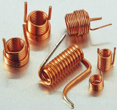
Inductor Coils
The inductor is a coil of wire; when electric current flows through the wire, it creates a magnetic field. When the wire has been given the shape of the coil, the shape is such that the field force is directed toward the core, hence increasing its magnetic properties.
The time-varying magnetic field, which is created by the inductor, tends to hold the magnetic energy, and when the current changes, the field induces some current back into the circuit to remain stable.
In terms of capacitors, the electric fields are created, and change in voltage is resisted, whereas inductors produce a magnetic field and resist the current changes. Since inductors can regulate current, they are used widely in many electronic applications.
To create an inductor coil, a special wire is used, and it is known as magnet wire. It looks like the usual wires but doesn’t have the usual rubber insulation. A magnet wire has a tough but thin coating made up of enamel, and it keeps the coil insulated without any interference to its inductance.
Types of Cores in an Inductor Coil
Iron Core
The iron core of the inductor coil is designed using a conducting material with an insulated copper wire that looks like a coil, and then it is wrapped around the iron core.
This material is a conducting one and hence helps amplify the magnetic field to improve the inductor. Therefore it carries out storing energy by a strong magnetic field. It is a better option than the air core despite having the same number of turns.
There are many advantages of an iron core. It has lower losses and a simple layout with a high Q factor, having large inductance despite having the same number of turns as the air core inductors; they offer a better inductance. However, it has sophisticated isolation.
Ceramic Core Inductor Coil
Ceramic material is a non-magnetic material, and the ceramic core coil provides a structure to the coil to allow the terminals to help sit upon it. The ceramic core coil also has a lower peak inductance and low magnetic permeability.
Ceramic core coil stores energy at a lesser rate and has a very low distortion rate. On the other hand, it provides reduced core losses.
Laminated Steel Core Inductor Coil
In a laminated core inductor could, the core is made with a bundle of thin sheets placed at the top of one another and then laminated to ensure tightness. The insulation layer adds electrical resistance, and the current loss in the inductor reduces the loss. These are used in high-power applications.
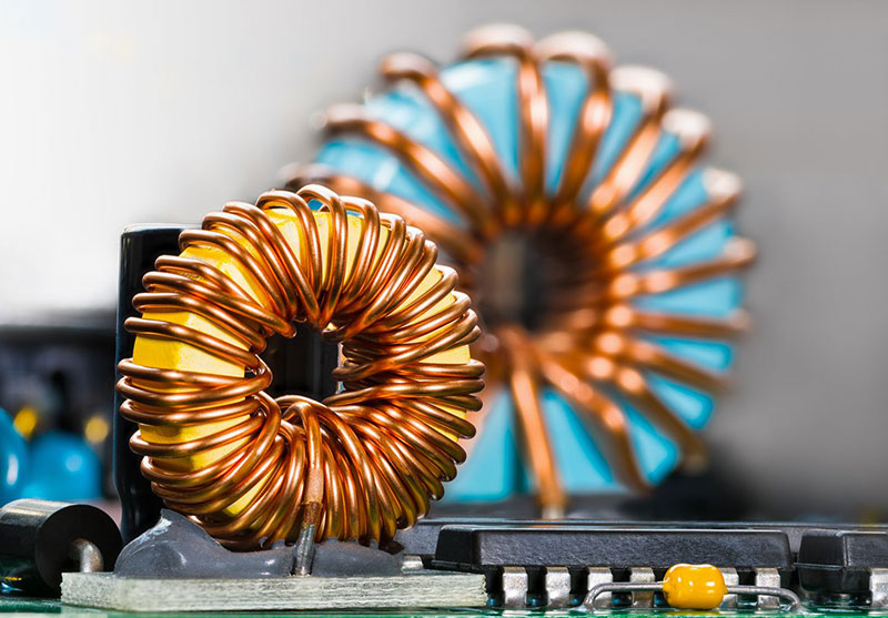
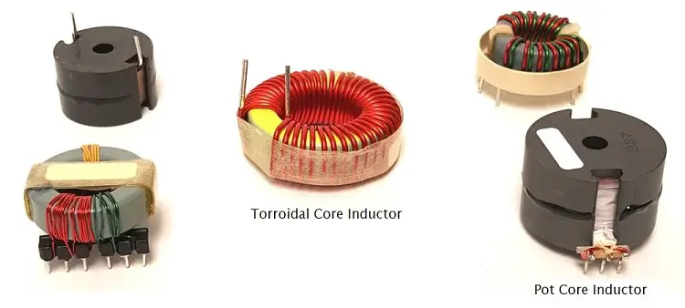
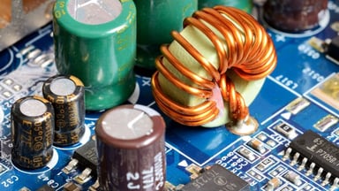
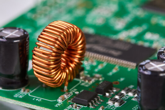
Toroidal Core Inductor Coils
The toroidal core inductor coil comprises a wire wrapped around the core with a surface shaped like a donut. It uses materials like powdered iron, ferrite, and tape wound. It offers a high result of couponing between the early saturation and winding.
The way this coil is arranged gives it minimal loss in the magnetic flux; hence, it offers high energy and high inductance even at low-frequency applications. The coil is used in air conditioners, telecommunications, and other components.
Inductor Applications
There are many applications of inductors, and they tend to cater to many purposes; some of these applications are discussed below:
Inductors in Electric Vehicles
When it comes to electric vehicles, there are many EMUs in the vehicles, and they contain DC-DC converters that tend to adjust the voltage of the battery to the optimum level. The power inductors work here as a critical component that will determine the converters’ performance in the vehicle’s EMUs.
The inductors work to allow electricity to flow freely, and it behaves like resistance for the alternating current. When used in correspondence with ICs that allow the DC-DC converters to let the induced voltage convert them to the desired level.
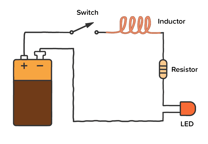
Inductors in DC Circuits
These are used to store energy by creating an electric field, and these are used in switches and power devices and produce a DC current flow.
The inductor coil stores energy and then supplies it into the circuit when the switch is off, allowing the output voltage to create the input voltage. The inductor changes the way DC circuits manage the flow of current.
Inductors for Power Factor Correction
In power factor correction, all styles of inductors work. However, toroidal inductors are best because they offer higher performance than other inductors. These use lesser volume, are less weight and tend to emit lower electromagnetic interference.
Inductors in Wireless Chagrining Coils
The process of wireless chagrining is dependent on electromagnetic induction; when the electricity flows in a coil, it creates a magnetic field that generates another electric current and the other coil, which is away. It is a form of wireless power transfer and uses electromotive force to provide electricity to portable devices.
Factors Affecting Inductance
Four factors affect the inductance in the inductors, and these are discussed below:
Number of turns
The number of turns a coil has determines the inductor’s inductance; the more turns a coil has, the higher the inductor’s inductance.
Length of the Coil
In the case of the inductance of the inductors, the length even matters. Even if the two coils have the same turns, the one with a shorter length will have more inductance, and the one with a longer length will have less inductance.
Due to the compact structure, the magnetic fields created become stronger and hence stretches out, eliminating the inductors oppose the diminishing power of the current.
Diameter of the Coil
The diameter of the coil in an inductor also determines the inductance; the more significant the diameter, the greater the inductor’s inductance.
The core of the Inductor
Some of them have a solid core within their center, and when a special core like a ferrite rod is used in the middle, the amount of inductance also increases. However, inductors that have no solid core have low inductance.
What is Self-inductance?
Self-inductance is the voltage induction in a wire that carries current when the current flow changes. When self-inductance occurs, the magnetic field is created by changing the current, and hence a self-induced voltage is created in the circuit.
Self-Resonant Frequency in a Circuit
In the same way, the self-resonant frequency is the frequency at which the capacitance of an inductor resonates with the ideal version of the inductor, resulting in a high impedance. The device at such frequency is no less than an open circuit.
What are Color ring inductors?
Color ring inductors are self-inducting components that, along with a capacitor and inductance coil, create resonant and filter circuits in the circuits, which comprise magnetic or hollow cores.
Conclusion
Inductors are a critical part of many applications used in electronics because of their electromotive force and their ability to hold energy. They do it by storing it, making them eminent for all electrical circuits.
After going through the guide above, you must have understood many things about inductors. If you have anything more to share, please do so in the comment box below.
