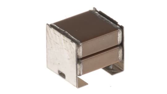
MLCC stands for multi-layer ceramic capacitors, passive components used in multiple electronic devices. Multi-layer ceramic capacitors mlccs work to charge and discharge electricity in a circuit temporarily.
In other words, multilayer ceramic capacitors carry out the task of regulating the flow of current in the circuits of electronic devices and help in avoiding electrical interference between different components on a circuit board.
A multi-layer ceramic capacitor is made of ceramic material. It is such a type of capacitor that controls the current amount flowing in a circuit and, at the same time, prevents noise generation and malfunction in electronic devices.
These capacitors are used in MLCC devices and play a significant role in ensuring that different electronic devices have high performance and integration. In this guide below, you will learn about different capacitor types and a detailed insight into multi-layer ceramic capacitors and their applications. So, if you are looking forward to gaining some understanding of capacitors, you must read below.
Types of Capacitors
There are three common types of capacitors, each having its applications and properties; these are discussed below:
Ceramic capacitors
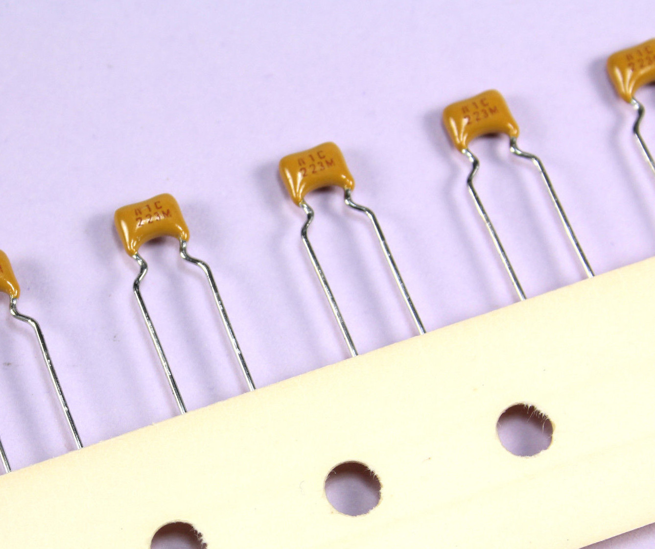
One of the most common types of capacitors is ceramic capacitors. They are widely used in many electric instruments due to their exceptional electrical characteristics, making them affordable and reliable. The ceramic capacitors comprise discs that are based on ceramic material. The ceramic material is a perfect dielectric since it has poor conductivity and supports electrostatic fields.
Ceramic capacitors are made of ceramic materials; hence, they are considered high dielectric constant materials. Therefore, they consist of more ceramic layers with sufficient layer thickness, with an electrode in the form of metal paste between the alternating layers.
Polymer capacitors
On the other hand, a polymer capacitor uses solid polymers in the form of electrolytes. These capacitors are beneficial because they comprise a very safe failure mode, are far more durable than electrolytic capacitors, and have lower losses.
They comprise an electrolyte made out of a conductive polymer solid rather than gel or liquid, which is usually present in other kinds of capacitors. Since they have solid electrolytes, the requirement of electrolyte drying doesn’t exist, which tends to make them more durable.
Polymer capacitors offer a lower level of series resistance. Hence, if the ripple current is high, the capacitors may withstand this situation. The capacitance value of polymer capacitors ranges between 10µF to 1mF. The voltage ratings of this capacitor are around 35V, and some of the capacitor models may have a voltage rating of 100V.
Aluminum electrolytic capacitors
Aluminum electrolytic capacitors are polarized capacitors, and the anode electrode of these capacitors is made using aluminum foil with its surface etched. The aluminum foil creates a thin dielectric layer that acts as an insulator. This layer is a layer of aluminum oxide, and over this layer is a layer of non-solid electrolyte which acts as a second electrode, also known as the cathode of this capacitor.
An aluminum electrolytic capacitor is widely used in many power electronics acting as a DC link capacitor. It can store energy in a strength-oriented manner, which is also ideal for applications needing hard discharge, such as a flash capacitor.
An aluminum electrolytic capacitor is used mainly in power supply, motherboards of computers, or applications requiring large capacitance values. The best part is that these capacitors have multiple shapes to cater to all applications.
These capacitors offer high voltage ratings that may go up to 600V, and compared to the other kinds of capacitors, it is relatively cheaper, and you can get the same level of voltage and capacitance. However, the current behavior of these capacitors is better than the polymer ones.
Advantages of Using MLCC Capacitors
MLCC capacitors are used widely in many devices, and plenty of reasons make them suitable. Some of the advantages of these capacitors are discussed below:
High capacitance values
As the technology progresses, the capacitance change in the capacitance values of MLCC capacitors has also increased and hence is getting suitable for most applications. The high capacitance of these capacitors, which is >10μF, allows the performance of these capacitors to cater to many applications that electrolytic capacitors and tantalum capacitors have catered.
Low equivalent series resistance (ESR)
Capacitors with minimum ESR are the most suitable option. These capacitors offer thermal stability as the issue of internal heating and power losses is inexistent. The capacitors with high ESR usually end up reducing the life of the capacitor itself. Hence, low ESR in a circuit design allows for a better ripple current in mlcc devices.
High reliability and durability
Capacitors are used in the circuit board of many electric devices, and their durability and reliability matter greatly. If a capacitor is not reliable or doesn’t last for a longer life span, it could damage the electric devices.
The MLCC capacitors, therefore, are very durable and long-lasting; hence, they can easily be used in many devices, declining with all kinds of extreme situations, be it high temperature or any other harsh condition faced by the device.
Low cost
Cost is always one of the essential concerns when it comes to investing in any electronic component. There are many capacitors, and each of them has its features. However, MLCC capacitors are suitable in all aspects as they provide excellent properties at a very low cost, so many MLCC devices incorporate these capacitors.
Miniaturization
In a circuit design, the miniature components are always key because these days, the trend of compact circuits is taking the lead as it ensures the production of compact devices. Hence, the MLCCs are even backed with sufficient miniaturization, making them suitable for compact circuit design. This results in cost savings and, at the same time, offers the same volume and results with a smaller size.
Capacitor Models
The different aspects of the multi-layer ceramic capacitors can be seen in other capacitor models, and some of these are discussed below:
Series and Parallel Connection
MLCC Capacitors in Series Connection
When capacitors are connected in series, they have equal currents flowing through them. Hence, every capacitor will also have an equal amount of electric charge, irrespective of its capacitance values.
This happens because the charge on one plate of the capacitor comes from the capacitor plate next to it, and hence in series, all the capacitors are connected so they have the same charge.
The total charge on the capacitors can be represented as follows, for instance, if there are three capacitors.
QT = Q1 = Q2 = Q3
Let’s take an example of three capacitors that are connected in series and let’s label them as C1, C2, and C3. In such a circuit, the capacitor C1 connects in a way that it has the left plate of the capacitor next to it then C2 is connected with its right-hand plate to the left of the third capacitor. In such a case, the capacitor C2 is isolated from the entire circuit, and this is a DC bias circuit.
In such a connection, the plate area decreases, and the drop of dc voltage across every capacitor will differ dependent on the capacitance values of every capacitor.
The total capacitance of the capacitors in the series circuit can be written as follows:
Ct= 1/C1 + 1/C2 + 1/C3
MLCC Capacitors in parallel Connection
In the other case, when multi-layer ceramic capacitors are connected in parallel, the capacitance of all the capacitors can be summed up to get the total capacitance. In such cases, when the capacitors are connected in parallel, the impact of these is that one single capacitor has the capacitance of the total plates of all the individual capacitors. This leads to an increased plate area and hence increased capacitance.
In case there are three MLCC capacitors in a circuit, C1, C2, and C3, the total capacitance could be represented by the below-given formula:
Ct = C1 + C2 + C3
Capacitance tolerances
The tolerance of ceramic capacitors is one of the very important considerations. The multi-layer ceramic capacitors that belong to class 1 have a lower tolerance level of around 1 percent.
On the other hand, the class 2 multi-layer ceramic capacitors have a higher tolerance of about 20 percent. The thermal stability in these capacitors is around a positive 15 percent or a negative 15 percent in terms of the operating temperature range.

Factors Affecting Capacitance
The capacitance values of a capacitor play an essential role in many ways when it comes to its performance, and certain factors may impact the capacitance values of a capacitor, and some of these are as follows:
Temperature
The change in the temperature range in the surrounding of the capacitor has an effect on its capacitance because the change in temperature range changes the dielectric properties. If the temperature around the capacitor changes to too cold or too hot, it will affect its operation.
The usual range for capacitors is -300C to +1250C in the nominal voltage ratings for a temperature not more than +700C in the capacitors.
Humidity
The humidity in the surroundings also has an effect on the capacitance values of a capacitor, and as the humidity in the surroundings increases, the capacitance of the capacitor also increases. Due to high humidity levels, the water content in the surroundings is also high, and hence this leads to an increase in the dielectric permittivity constant.
In case of higher humidity levels, the dielectric layers of the capacitors tend to absorb the water content, and hence the dielectric constant increases, which allows the capacitance to increase as well. On the other hand, less humidity means less content of water absorption by the dielectric, and hence the dielectric constant decreases, leading to a lower capacitance value.
Voltage
The capacitance of a capacitor is impacted by the voltage too. When high voltage passes through the capacitor, the capacitance value also increases. A higher charge is fed through high voltage, so the capacitance increases.
When there is a voltage change, that is, the voltage increase or decreases, the capacitor tends to resist this change, and hence it draws the current from the source it is supplied, and therefore this is the reaction on the capacitance. The voltage across the capacitor must be increased so that more energy is being stored in the capacitor. In the case of lower voltages, the capacitance is also less, and hence lesser energy is stored.
Dielectric Between Plates
Capacitance change is linked to the dielectric material used; when the dielectric has a higher level of permittivity, the capacitance is more; when it has lesser permittivity, the capacitance is less.
Area of Plates
The plate area is also a factor that impacts the capacitance of a capacitor. In the case of the greater area of the plate, the capacitance is also more significant, and in the case of a lesser area, it is less. Due to the larger area, the field flux is more, and hence more charges are present on the plate leading to high voltage and high capacitance.

MLCC Capacitors in DC-DC Converters
These ceramic capacitors carry out some main tasks, including coupling in a circuit, decoupling, filtering, and smoothing.
When it comes to ceramic capacitors are widely used in dc-dc convertor output as well as input filters. The main reason for opting for them is their low ESR, affordable cost, and equivalent series inductance. Hence because of these reasons and their long terms reliability, they are suitable for many applications like power electronics, automotive electronics, and much more.
Output capacitor for step-down DC-DC converter
As the use of ICs is becoming popular in recent times, the use of low power supply voltage is also increasing, and since ICs need more current, this has helped them achieve that. To ensure compatibility between the low voltage ratings and high currents, the distributed power supply systems have placed the DC-DC converters close to the loads, which is used widely. An example of such a scenario can be seen in ICs from the intermediate bus converter.
In DC-DC convertors, many capacitors are used. Among various options, the MLCC capacitors have proven to be an ideal choice for their excellent properties, which are compact size, low profile, and low ESR.
The output capacitor in ideal situations must be sufficient to have the right energy storage and low impedance followed by appropriate frequency responses. If we look at the tantalum and polymer capacitors, they have a larger value followed by lower ESR, but they are very expensive.
On the other hand, electrolytic capacitors offer sufficient capacitance value at an affordable price but have a larger ESR; hence, they are unsuitable for required output performance.
Therefore, ceramic capacitors are better as they have a lower ESL and low ESR, which offers excellent performance. However, they might offer some limitations on the capacitor size.
Ripple voltage reduction
The ripple voltage is the AC voltage apparent on the DC voltage. Using ripple voltage leads to the conversion of AC voltage to DC voltage. However, it doesn’t eliminate the AC voltage.
In the case of ceramic capacitors, they are widely suitable when it comes to reduction in ripple voltage due to the lower ESR and lower ESL when compared to the other kinds of capacitors. Usually, the small sized capacitor generally offers low impedance at high voltage ratings.
These capacitors have lower ESR to reduce the DC-DC convertors’ output voltage. If further reduction in the ripple voltage is needed, that can be reduced by decreasing the current ripple that the output capacitor absorbs by force.
State-of-the-Art in Ceramics
Applications that need high temperatures require a suitable capacitor, and here the dielectric ceramic capacitors prove to be a suitable solution to ensure power integrity.
Ceramics that are lead-based, like La-doped zircon-ate titan-ate lead, offers excellent energy storage. Still, the primary concern is their toxicity; hence, using them in consumer electronics could be a problem. Such devices require a lead-free solution of capacitors.
Lead-free compositions are required for consumer electronics because they are not toxic enough. These aspects form to be state of the art capacitors and help in deciding as to which ceramic capacitors must be chosen. There are different aspects in ceramic capacitors which may be either lead-based or not, and these are discussed below:
Lead-based ceramics
The lead-based ceramic devices are used in commercial applications and carry out storing energy. They are suitable for high-power pulse capacitors and offer excellent Wrec and η. (98−101)
Some of the compositions of lead-based ceramics are as follows and prove to be suitable for storing energy based on electronic circuits.
1. (Pb0.89Ba0.08La0.02) (Zr0.7Sn0.27Ti0.03) O3
2. Pb0.97La0.02 (Zr0.58Sn0.35Ti0.07) O3
3. (Pb0.93Ba0.04La0.02) (Zr0.65Sn0.3Ti0.05) O3–0.005Mn2O3
4. (Pb0.87Ba0.1La0.02) (Zr0.65Sn0.3Ti0.05) O3–0.75Y
5. (Pb0.91La0.06) (Zr0.96Ti0.04) O3–1.0 mol % MnCO3
Lead-Based Relaxor-Ferroelectrics
Multiple leads-based relaxor ferroelectrics have been known for being suitable to have opted as capacitors for energy storage. The relaxation behavior and properties for storing energy were investigated for the (1–x) PMN–xPT ceramic, which led to obtaining Wrec ∼ 0.47 J cm–3 comprising exceptional thermal stability.
Lead-Based Anti-ferroelectrics
Similarly, when it comes to lead-based anti-ferroelectrics, the first was known to be PbZrO3 which can exhibit the P-E hysteresis loop that is lower than TC. However, this option’s limitation comprises having a switching field that limits the ability to store energy. However, choosing to substitute helps reduce the switching field and helps overcome this limitation.
In this case, the best options in terms of compositions based on PbZrO3 are (Pb, La) (Zr, Ti) O3 (PLZT); (112−115), (Pb, La) (Zr, Sn, Ti) O3 (PLZST); (116−129), (Pb, La) (Zr, Sn) O3 (PLZS). (130,131)
Non-leaded ceramics
In the past few years, researchers have looked forward to opting for lead-free electroceramics because the problem of lead toxicity was an increasing concern.
Since then, there has been an improvement in making their performance improved in the process of storing energy so that they can easily replace lead-based ceramic compositions. The different kinds of lead-free ceramics which can replace PLZT in applications where storing energy via capacitor is needed are usually based on ST, KNN, NBT, AgNbO3, NN, and many more.
BaTiO3-Based Ceramics
Dielectric ceramics based on BT have dominated the ceramic capacitors market for decades, and their energy-storing performance can be improved in different ways. They can be substituted with oxide so that the BDS improves, for instance, using Al2O3, SiO2, etc.
Multiple sintering techniques may also be used, like SPS or cold sintering, that lead to an increase in the density of the ceramic in controlling the growth of grains. Adding sinters like ZnNb2O6 also helps increase the density of the ceramic capacitors. Above all, the best approach is introducing the Bi-based perovskite member with many cat-ions on its B-site.
SrTiO3-Based Ceramics
ST is one of the ideal candidates, known for storing energy in electrical applications, and having exemplary electrical characteristics like high permittivity and low dielectric loss at room temperature are key points that make it suitable. Several methods are adopted to improve the energy storage of the ceramics based on ST. the first option could be doping it with Bar, Mg, Dy, Bi, and Ce on site A or using the doping of Mn or Sn on site B.
Another method is using sintering like ZnO, Sio2, BaCu, AlzO3 etc., using multiple sintering techniques like microwave sintering or adding complex end members like NBT–Ba(Al0.5Nb0.5)O3, Bi(Mg0.5Hf0.5)O3 also helps in improving the performance of these ceramics.
BiFeO3-Based Ceramics
Ceramics based on BF are known to be the best multi-ferroic but, at the same time, are opted for applications that require a high-temperature range of ferroelectric or piezoelectric (barrier layer capacitors) because they possess a high TC followed by their spontaneous polarization being large.
When these are compared to the other ceramics, which are lead-free, they were initially not considered as being the best option because their leakage current is a higher one. Hence, they may restrict the density of energy. Since the dopants have been introduced in this state, they can now be used widely as the best energy-storing ceramics in multiple electrical applications.
The discussion over whether lead-based ceramic capacitors are suitable or lead-free ones has been ongoing for many years. However, the performance of the lead-based ceramic compositions has proven to be far much better than the ones with lead-free.
Lead-free ceramics may also be used, but obviously, they need an excessive series of processes, one after the other, that brings about the required level of performance and capacity to store energy. In the near future, considering the cost of lead-free electroceramics, their safety, and performance will soon overtake lead-based electroceramics and will be seen mostly in all applications.

Size and packaging
The analysis of the size of MLCC capacitors comprises a number with 4 digits; the first two digits represent the length of the MLCC, and the last two digits represent the width of the MLCC.
The range of DC bias voltage in the surface mount multi-layer ceramic capacitors vary. At the same time, there are multiple sizes ranging between 0603 to 8060, which is ideal for all kinds of applications that are general purpose.
When it comes to packaging these ceramic capacitors, advanced techniques are being employed that use silicon wafers that are stacked, and other aspects like silicon vias, micro bumps, and ceramic substrates are all used to ensure novel decoupling capacitors are packed, and low inductance design is also ensured in this case so that the current flows smoothly.
MLCC Capacitor Failure Mechanisms
Some reasons form to cause failure mechanism on the multilayer ceramic capacitors, and some of these are as follows:
Electrical and mechanical stress
The failure in the multi-layer ceramic capacitor is usually because of the short circuit that is caused due to the ceramic cracks that spread on the ends of the device. It usually starts when PCB assembly is carried out, and mechanical stress occurs due to soldering.
The position of the MLCCs on the PCB also plays a role in causing this stress. When the placement is close to the edge during the process of de-paneling, the MLCC may face stress which causes them to fail.
Hence, one must eliminate excessive mechanical stress during the de-paneling or surface mount process. Moreover, the capacitors used in the automotive electronics and aerospace industry are manufactured with soft resin, eliminating the pressed on the ends and protecting them against mechanical stress. Electrical stress is also a common stress faced by MLCC devices, and it happens because of low insulation resistance or low nominal capacitance value.
Temperature and humidity
Humidity and temperature also have an impact on the MLCCs. In case when the humidity is high, droplets of water appear on the capacitor’s surface, and hence the insulation resistance reduces.
In case of high temperature and humidity, the capacitors do have a negative influence, and it ends up wearing it out or making it loses its ability to perform properly. In the case of semi-sealed capacitors, they may face a dielectric breakdown. Due to high temperature and humidity, there may also be an electrical failure in the capacitor. It may cause the capacitor to burn out or rupture due to the excessive electrical stress caused.
Testing strategies and fault diagnosis
When a ceramic capacitor is installed over the circuit boards, the failure to test the functionality and identification of faults is also one of the main reasons that cause the failure mechanism of the capacitors.
Due to the inappropriate soldering process, a lot of stress is being put on the capacitors. They can’t handle this pressure as ceramic capacitors and fail to perform. During the assembly process of all circuit boards, the capacitors must be appropriately focused so that no such situation occurs.
Fracture analysis
How brittle the dielectric determines the failure mechanisms of laminated ceramic capacitors. Since a laminated ceramic capacitor is fused into the circuit board directly, it can handle mechanical stress. However, the leaded ceramic capacitors may handle it because of the pins on their edges; hence, the laminated capacitor may rupture.
The discharge arc will be formed in case of a fracture in the laminated ceramic capacitor. It will lie between electrodes, causing a failure in the capacitor due to the lower electrode insulation separation compared to the breakdown voltage.
To reduce the chances of mechanical fracture in the laminated ceramic capacitor, the circuit board’s bending must be minimized, which helps reduce the stress on the board. A capacitor packed in a small size may reduce the mechanical stress presented in the laminated ceramic capacitor. Adding various parallel connections could be of great help in this case.
Electrode terminal melting
In the case of wave soldering, the chance of electrode terminals melting is high. It happens because the contact between the laminated ceramic capacitors during the wave soldering is very long, followed by a very high-temperature soldering process that causes the terminals to melt. This hassle of melting of electrode terminal can be resolved using other welding methods or wave soldering as little as possible.
Recommended Products for MLCC Replacement
There could be instances when you might look forward to having a replacement of the MLCCs, and in this case, you can consider the points shared below:
Manufacturers and suppliers
In applications where smoothing and decoupling capacitors are needed, the name of aluminum electrolytic capacitors and tantalum capacitors has been taking the lead due to their large capacitance.
Since the inception of 5G technology, the demand for multi-layer ceramic capacitors has been growing and also has been facing a shortage. Hence a replacement of MLCCs is needed. The alternative of these MLCCS can be found in the portfolio of Panasonic Industry as it is one of the leading manufacturers of polymer capacitors. The SP-Caps and the OS-Con are options to consider from this manufacturer.
Product selection and specifications
Choosing polymer capacitors offers collaboration with larger capacitance and exceptional bias characteristics, ensuring they perform better than the MLCCS. The capacitors manufactured by Panasonic Industry are always relevant for consumers who want these polymer capacitors employed on a PCB and wish to save money and space.
These polymer capacitors offer a long terms stability, are safe to use, offer exceptional characteristics, and are far much reliable.
Conclusion
Multi-layer ceramic capacitor models are far more popular nowadays because of their exceptional electrical characteristics. They have been performing well and have always received positive feedback in all the industries they have been used. Also, with time, innovations and developments are taking place, making these capacitors low-cost, more efficient, and capable of taking lesser space.
These days, multiple industries have depended on ceramic capacitors like aerospace, automobile, and power electronics. These capacitors are suitable for use when low-level capacitance is needed. These can be used in op-amp circuits as bypass capacitors, reducing noise and temporarily charging it.
You must know every detail now because you have learned many things about MLCCs. However, if you have more information to share, please comment in the box below.
