Photo by tnfeez desgin on Pexels
How to Pick the Right Electronic Components for Your Project?

Photo by tnfeez desgin on Pexels
Choosing the right electronic components for your project can be challenging with the vast array of options available for component selection. It is one of the most challenging aspects of starting a new project. This guide will cover key considerations you can make to help you correctly select electronic components for your project to make a significant difference in its performance and functionality.
- Decide on the Type of Project You Want to Create
Deciding on the type of project you want to create helps to establish a clear project goal and purpose, making it easier to plan and execute the project and measure its success after completion.
It can also impact the resources and materials required for the project. For example, if your project requires many specialized components or materials, it may be more expensive or time-consuming to build.
Here are some steps you can follow to help you decide on the type of project you want to create:
- Define Your Project Purpose: Think about the purpose or goal of your project. What do you want it to do? What is your target market? Knowing your project purpose will help you narrow down the type of electronic components it will need to achieve it.
- Consider the Project Constraints: What resources do you have available (e.g., budget, space, tools)? What are the limitations of your mechanical parameters (e.g., size, weight, location)? Consider these constraints and more to help determine which parts are practical and feasible.
- Other Considerations: Will an automated PCB assembling route be convenient, or should you opt for manual assembly? How will you handle power management? Do you need to consult reference designs to meet a specific standard or a benchmark?
Will you be going for a complex application circuit? Many times the application circuit’s complexity drives the component selection. You also want to know whether you will use electronic devices from a previously proven design. Although this could help reduce the risk of design issues, you may miss out on the advantage of new parts.
- Define the Circuit Requirements for Your Project
This involves determining the components you need to build the circuit for your project. It also includes defining the circuit topology and specific values of the electrical parameters that characterize the performance and behavior of the components. Examples include the input voltage range, output voltage accuracy, power rating, light load efficiency, resistance values, capacitance values, and other critical parameters.
- Create a Block Diagram for Your Circuit
A block diagram is a high-level representation of a system or circuit showing the functional components and their interactions without the electrical connections. It is a simplified graphical representation that typically uses rectangular blocks and arrows to indicate the flow of information or signal between the components.
To create a block diagram of your circuit, sketch the main functional blocks and their flow of information to illustrate the overall circuit layout. You then organize them into functional groups, draw interconnections between the blocks with arrows, label the blocks, and add annotations to explain the function of each block or circuit operation.
- Research the Electronic Components That Meet Your Needs
Once you have identified the purpose of your project, determined the components that meet your circuit requirements, and illustrated the circuit with a detailed block diagram, the next thing is to research each of them. This includes exploring different options available with various suppliers. Popular ones include RS Components, DigiKey, Farnell, Mouser, and Element14.
There are many different components with different options and from various manufacturers, each with its specific capabilities, features, availability, cost, and other factors. Some factors to consider when researching the best options for the components that best suit your needs include:
- Availability
Some components may be unavailable to purchase due to being out of stock or discontinued. Therefore, verifying their availability is essential before you commit to using them in your project.
Verifying their availability will help to ensure your project is completed on time and within budget. We also recommended having a few alternatives in mind for each component. For example, having a pin-compatible alternative, just in case the primary choice is not available or too expensive.
- Price
The cost of electronic parts can be affected by manufacturing difficulties, such as precision of value or measurement, operating voltage range, current rating, operating temperature, and voltage isolation.
As such, some components are usually more expensive when they have a larger current and voltage range, higher temperature tolerance, or higher blocking voltage. The harder it is to manufacture a part, the more expensive it will be.
Also, parts that have a broader range, higher temperature tolerance, and higher blocking voltage will be more expensive. Consider the price and cost of every component in your circuit, and choose parts with the most affordable cost that meet the design requirements without compromising on quality. Remember to also factor in shipping costs in your decision.
It is essential to consider more than just the cost of the component. You should consider other factors that can add value to the project in the long run, such as the quality and how power efficient and reliable it is in terms of performance.
For example, a low-priced component with lower quality or reliability may cost more in the long run if it needs frequent replacement. However, an expensive part with higher quality and reliability may provide higher overall value by reducing maintenance and replacement costs.
- Quality
The quality of components can vary between manufacturers and suppliers. Therefore, when selecting parts for your project, it is essential to consider their quality. Choosing lower-quality parts may result in poor performance or project failure.
Low-quality components may be cheaper, as the manufacturers or suppliers usually sell them at a lower cost to make them more appealing to buyers. Although it may be tempting to choose the lowest-cost option, doing so may result in poor performance or project failure.
- Specifications
Component manufacturers may change or enhance some components over time, and the published specifications for the parts you choose may be an older version. As such, you need to verify the recency of the published specifications for your selected components.
Doing so ensures that the components meet the latest standards with critical specifications suitable for your project. Newer specifications may include essential updates or changes that address known issues with the part or improve its overall performance.
Outdated specifications may not reflect the updated features or current capabilities, which can lead to compatibility issues or suboptimal performance in the final product.
Examples of specifications to verify for recency include the supply voltage, power consumption/output, operating temperature range, signaling standards, life cycle status, and all the parameters concerned with your circuit.
- PCB Footprint
Ensure that the physical layout or PCB footprint of the components you choose matches your PCB layout. This includes the size, shape, and location of the connecting pins. If the PCB package is not the right fit, the component may not fit the PCB design.
A package that does not match the PCB design can cause difficulty when soldering the component onto the board, get damaged, or even damage the board. In the worst case, you may need to redesign the overall PCB real estate, which could be costly and time-consuming.
- IPC PCB Classification
You may also need to ensure the components meet the IPC Class of your PCB (Class 1, 2, or 3), based on the standards IPC-7351B, IPC-CM-770E, and IPC-D-330, set by the Interprocess Communication (IPC).
These classes correspond to specific environmental conditions and performance requirements, such as temperature and humidity range, vibration levels, altitude, radiation, and chemical exposure.
The electronic components you choose must match your PCB class to ensure that they can operate reliably and efficiently under the required environmental conditions and performance requirements.
Class 1 PCBs are for non-critical applications that do not require high levels of performance or reliability. You can find them in generally cheap consumer electronics or low-power applications, some inexpensive toasters, and small toys.
On the other hand, Class 2 PCBs are for moderately demanding applications that require higher performance and reliability than class 1 PCBs. You can find them in communication devices, automobiles, air conditioners, and laptops.
Lastly, Class 3 PCBs are for high-reliability, high-performance applications that require the highest levels of performance and reliability. You can find them in medicine, aerospace, defense, and other critical applications.
- Manufacturer/Supplier Reputation and Reliability
Research reputable and reliable component manufacturers/suppliers. This is important to ensure that components get delivered on time and are of good quality so that you can meet your project development and mass production deadlines.
Also, aim to work with manufacturers/suppliers with good online Bill of Materials (BOM) tools, evaluation board support, good shipping practices, and excellent customer service. They can help boost your efficiency in selecting and ordering the parts needed for your project.
Having technical support is also essential. Some manufacturers provide design review facilities, which is helpful for customers designing a circuit for the first time with their parts. Working with a manufacturer like that will be a good value-add.
- Design a Schematic Diagram for Your Project
Schematic diagrams are designs or plans that represent the circuit topology of your project or the way the electronic components are electrically connected to make the circuit function. The Schematic diagram sets the foundation for the project and helps address any potential errors or issues that may cause problems later on.
Designing a schematic diagram for your project involves using the symbols of the components you researched to be suitable for the project. The component symbols indicate their position and connections in the circuit to help visualize how they will be connected and integrated. It also shows how the project will function as a whole.
Also, the design process is typically done on a virtual circuit board using various types of schematic design software tools, some of which double as circuit simulation software tools. Some common ones include LTspice, Proteus, Multisim, CircuitMaker, KiCAD, Eagle, and Fritzing.
When designing your project schematic, you should also consider the user interface components for your project. Will it have buttons, switches, a display, or sensors? How will users interact with it? Selecting the appropriate interface components will help make your project user-friendly and intuitive.
- Ensure All the Components Are Compatible With Each Other
Aside from selecting the right electronic components for a project, checking if they are compatible with each other is another essential step that ensures the functionality of the project. These components can have specific requirements, such as voltage and amperage, which are necessary for the project to function as intended.
Good compatibility will ensure that all the parts work together seamlessly to achieve the desired functionality and performance of the project. One way to ensure this is by testing the functionality of the schematic using simulation software such as any of the software mentioned earlier.
They will allow you to simulate the circuit behavior and test it in a virtual environment to help you identify any errors or compatibility issues in the design before building the physical project. For example, if you are designing a circuit that requires a specific voltage or current range, you can use simulation software to ensure that the chosen components will handle that range.
You can also test how power efficient the circuit is and its response to different temperature or humidity conditions to ensure that the chosen components will operate within the required operating environment.
Another way to verify that the components you choose are compatible with each other and meet your project requirements is by building a prototype and testing it. You can increase your chances of having a successful project by choosing components that meet your circuit requirements and verifying their compatibility.
- Assemble the Components According to the Schematic Diagram

Photo by Blaz Erzetic from Pexels
After researching and ordering all the necessary components you need, the next step is to purchase them. It is important to carefully check that you have all the parts before beginning assembly. It can be difficult to troubleshoot problems later if you miss a crucial component.
Once you have gathered all parts, you can begin laying them out according to the schematic diagram. Make sure to take note of any polarity markings on the components indicating their orientation in the circuit.
The next step is to begin soldering the components together. This is a crucial step in assembling electronic circuits. It ensures that the parts are securely connected and that the circuit functions as intended.
While soldering, it is essential to pay close attention to the placement and orientation of the components. Even small mistakes, such as reversing the diode or transistor orientation, can cause a circuit to malfunction. Also, double-check the schematic diagram as you work to ensure that you assemble everything correctly.
- Test Your Project to Make Sure It Functions as Intended
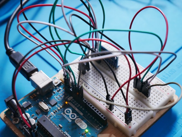
Photo by Vishnu Mohanan on Unsplash
Begin by performing a visual inspection of your project. This includes looking for any obvious signs of damage or defects, such as broken components, loose wires, or other issues. It is essential to address any issues faced during the visual inspection before proceeding with further testing.
Do a power-on test on the project. Connect power to the project and observe its behavior. This can help to identify any issues related to power supply, such as problems with voltage regulation or over-voltage protection. It is also essential to check that all the LEDs and other indicators are working.
After the power-on test, you should consider performing functional testing. This involves testing the various functions of your project to ensure that they are working correctly. Also, having a detailed test plan and procedures is essential to ensure that all the functionalities undergo testing.
Another test you can perform is stress testing. This involves testing the project under extreme conditions that may affect its performance, such as high temperatures, high humidity, or other factors. Stress testing can help to identify any issues that may not be apparent during regular operation and ensure your project is reliable.
- Troubleshoot Any Problems That May Arise
This may involve performing a visual inspection of the project and testing it with a multimeter or using other diagnostic tools to determine the cause of the problem. It is essential to carefully observe how the project behaves and note any symptoms indicating a problem.
Once you identify the problem, diagnosing the cause is next. This may involve consulting your schematic diagram and datasheets or consulting an external-experienced engineer. It may also include testing different components or subsystems to narrow down the cause of the problem.
If you can successfully diagnose the problem, you can understand how to make repairs or adjustments. It may involve replacing a faulty component, adjusting a circuit, or making other changes to the project to correct the problem. Be cautious when making repairs or adjustments, as mistakes can cause further problems or damage the project.
It is essential to test the project again using some of the previous steps discussed, such as performing power-on or functional testing. This will help to confirm that you have resolved the problem and that the project is working as intended.
- Document Test Results and Problems Solved
It is essential to document the results of the tests you conduct. This includes recording any issues found during the testing process and the steps you took to address them. The documentation will be helpful for future reference and troubleshooting any similar problems that may arise later.
Conclusion
With all the electronic component selection guidelines discussed, you should be well on track to picking the perfect components for your project to ensure that it runs smoothly and fulfills its purpose. Note that this is an ongoing process, and as technology advances, you should stay updated on the latest options available to give your project the best chance of success.
Decide on the Type of Project You Want to Create
Deciding on the type of project you want to create helps to establish a clear project goal and purpose, making it easier to plan and execute the project and measure its success after completion.
It can also impact the resources and materials required for the project. For example, if your project requires many specialized components or materials, it may be more expensive or time-consuming to build.
Here are some steps you can follow to help you decide on the type of project you want to create:
Define Your Project Purpose: Think about the purpose or goal of your project. What do you want it to do? What is your target market? Knowing your project purpose will help you narrow down the type of electronic components it will need to achieve it.
Consider the Project Constraints: What resources do you have available (e.g., budget, space, tools)? What are the limitations of your mechanical parameters (e.g., size, weight, location)? Consider these constraints and more to help determine which parts are practical and feasible.
Other Considerations: Will an automated PCB assembling route be convenient, or should you opt for manual assembly? How will you handle power management? Do you need to consult reference designs to meet a specific standard or a benchmark?
Will you be going for a complex application circuit? Many times the application circuit’s complexity drives the component selection. You also want to know whether you will use electronic devices from a previously proven design. Although this could help reduce the risk of design issues, you may miss out on the advantage of new parts.
Define the Circuit Requirements for Your Project
This involves determining the components you need to build the circuit for your project. It also includes defining the circuit topology and specific values of the electrical parameters that characterize the performance and behavior of the components. Examples include the input voltage range, output voltage accuracy, power rating, light load efficiency, resistance values, capacitance values, and other critical parameters.
Create a Block Diagram for Your Circuit
A block diagram is a high-level representation of a system or circuit showing the functional components and their interactions without the electrical connections. It is a simplified graphical representation that typically uses rectangular blocks and arrows to indicate the flow of information or signal between the components.
To create a block diagram of your circuit, sketch the main functional blocks and their flow of information to illustrate the overall circuit layout. You then organize them into functional groups, draw interconnections between the blocks with arrows, label the blocks, and add annotations to explain the function of each block or circuit operation.
Research the Electronic Components That Meet Your Needs
Once you have identified the purpose of your project, determined the components that meet your circuit requirements, and illustrated the circuit with a detailed block diagram, the next thing is to research each of them. This includes exploring different options available with various suppliers. Popular ones include RS Components, DigiKey, Farnell, Mouser, and Element14.
There are many different components with different options and from various manufacturers, each with its specific capabilities, features, availability, cost, and other factors. Some factors to consider when researching the best options for the components that best suit your needs include:
Availability
Some components may be unavailable to purchase due to being out of stock or discontinued. Therefore, verifying their availability is essential before you commit to using them in your project.
Verifying their availability will help to ensure your project is completed on time and within budget. We also recommended having a few alternatives in mind for each component. For example, having a pin-compatible alternative, just in case the primary choice is not available or too expensive.
Price
The cost of electronic parts can be affected by manufacturing difficulties, such as precision of value or measurement, operating voltage range, current rating, operating temperature, and voltage isolation.
As such, some components are usually more expensive when they have a larger current and voltage range, higher temperature tolerance, or higher blocking voltage. The harder it is to manufacture a part, the more expensive it will be.
Also, parts that have a broader range, higher temperature tolerance, and higher blocking voltage will be more expensive. Consider the price and cost of every component in your circuit, and choose parts with the most affordable cost that meet the design requirements without compromising on quality. Remember to also factor in shipping costs in your decision.
It is essential to consider more than just the cost of the component. You should consider other factors that can add value to the project in the long run, such as the quality and how power efficient and reliable it is in terms of performance.
For example, a low-priced component with lower quality or reliability may cost more in the long run if it needs frequent replacement. However, an expensive part with higher quality and reliability may provide higher overall value by reducing maintenance and replacement costs.
Quality
The quality of components can vary between manufacturers and suppliers. Therefore, when selecting parts for your project, it is essential to consider their quality. Choosing lower-quality parts may result in poor performance or project failure.
Low-quality components may be cheaper, as the manufacturers or suppliers usually sell them at a lower cost to make them more appealing to buyers. Although it may be tempting to choose the lowest-cost option, doing so may result in poor performance or project failure.
Specifications
Component manufacturers may change or enhance some components over time, and the published specifications for the parts you choose may be an older version. As such, you need to verify the recency of the published specifications for your selected components.
Doing so ensures that the components meet the latest standards with critical specifications suitable for your project. Newer specifications may include essential updates or changes that address known issues with the part or improve its overall performance.
Outdated specifications may not reflect the updated features or current capabilities, which can lead to compatibility issues or suboptimal performance in the final product.
Examples of specifications to verify for recency include the supply voltage, power consumption/output, operating temperature range, signaling standards, life cycle status, and all the parameters concerned with your circuit.
PCB Footprint
Ensure that the physical layout or PCB footprint of the components you choose matches your PCB layout. This includes the size, shape, and location of the connecting pins. If the PCB package is not the right fit, the component may not fit the PCB design.
A package that does not match the PCB design can cause difficulty when soldering the component onto the board, get damaged, or even damage the board. In the worst case, you may need to redesign the overall PCB real estate, which could be costly and time-consuming.
IPC PCB Classification
You may also need to ensure the components meet the IPC Class of your PCB (Class 1, 2, or 3), based on the standards IPC-7351B, IPC-CM-770E, and IPC-D-330, set by the Interprocess Communication (IPC).
These classes correspond to specific environmental conditions and performance requirements, such as temperature and humidity range, vibration levels, altitude, radiation, and chemical exposure.
The electronic components you choose must match your PCB class to ensure that they can operate reliably and efficiently under the required environmental conditions and performance requirements.
Class 1 PCBs are for non-critical applications that do not require high levels of performance or reliability. You can find them in generally cheap consumer electronics or low-power applications, some inexpensive toasters, and small toys.
On the other hand, Class 2 PCBs are for moderately demanding applications that require higher performance and reliability than class 1 PCBs. You can find them in communication devices, automobiles, air conditioners, and laptops.
Lastly, Class 3 PCBs are for high-reliability, high-performance applications that require the highest levels of performance and reliability. You can find them in medicine, aerospace, defense, and other critical applications.
Manufacturer/Supplier Reputation and Reliability
Research reputable and reliable component manufacturers/suppliers. This is important to ensure that components get delivered on time and are of good quality so that you can meet your project development and mass production deadlines.
Also, aim to work with manufacturers/suppliers with good online Bill of Materials (BOM) tools, evaluation board support, good shipping practices, and excellent customer service. They can help boost your efficiency in selecting and ordering the parts needed for your project.
Having technical support is also essential. Some manufacturers provide design review facilities, which is helpful for customers designing a circuit for the first time with their parts. Working with a manufacturer like that will be a good value-add.
Design a Schematic Diagram for Your Project
Schematic diagrams are designs or plans that represent the circuit topology of your project or the way the electronic components are electrically connected to make the circuit function. The Schematic diagram sets the foundation for the project and helps address any potential errors or issues that may cause problems later on.
Designing a schematic diagram for your project involves using the symbols of the components you researched to be suitable for the project. The component symbols indicate their position and connections in the circuit to help visualize how they will be connected and integrated. It also shows how the project will function as a whole.
Also, the design process is typically done on a virtual circuit board using various types of schematic design software tools, some of which double as circuit simulation software tools. Some common ones include LTspice, Proteus, Multisim, CircuitMaker, KiCAD, Eagle, and Fritzing.
When designing your project schematic, you should also consider the user interface components for your project. Will it have buttons, switches, a display, or sensors? How will users interact with it? Selecting the appropriate interface components will help make your project user-friendly and intuitive.
Ensure All the Components Are Compatible With Each Other
Aside from selecting the right electronic components for a project, checking if they are compatible with each other is another essential step that ensures the functionality of the project. These components can have specific requirements, such as voltage and amperage, which are necessary for the project to function as intended.
Good compatibility will ensure that all the parts work together seamlessly to achieve the desired functionality and performance of the project. One way to ensure this is by testing the functionality of the schematic using simulation software such as any of the software mentioned earlier.
They will allow you to simulate the circuit behavior and test it in a virtual environment to help you identify any errors or compatibility issues in the design before building the physical project. For example, if you are designing a circuit that requires a specific voltage or current range, you can use simulation software to ensure that the chosen components will handle that range.
You can also test how power efficient the circuit is and its response to different temperature or humidity conditions to ensure that the chosen components will operate within the required operating environment.
Another way to verify that the components you choose are compatible with each other and meet your project requirements is by building a prototype and testing it. You can increase your chances of having a successful project by choosing components that meet your circuit requirements and verifying their compatibility.
Assemble the Components According to the Schematic Diagram
Photo by Blaz Erzetic from Pexels
After researching and ordering all the necessary components you need, the next step is to purchase them. It is important to carefully check that you have all the parts before beginning assembly. It can be difficult to troubleshoot problems later if you miss a crucial component.
Once you have gathered all parts, you can begin laying them out according to the schematic diagram. Make sure to take note of any polarity markings on the components indicating their orientation in the circuit.
The next step is to begin soldering the components together. This is a crucial step in assembling electronic circuits. It ensures that the parts are securely connected and that the circuit functions as intended.
While soldering, it is essential to pay close attention to the placement and orientation of the components. Even small mistakes, such as reversing the diode or transistor orientation, can cause a circuit to malfunction. Also, double-check the schematic diagram as you work to ensure that you assemble everything correctly.
Test Your Project to Make Sure It Functions as Intended
Photo by Vishnu Mohanan on Unsplash
Begin by performing a visual inspection of your project. This includes looking for any obvious signs of damage or defects, such as broken components, loose wires, or other issues. It is essential to address any issues faced during the visual inspection before proceeding with further testing.
Do a power-on test on the project. Connect power to the project and observe its behavior. This can help to identify any issues related to power supply, such as problems with voltage regulation or over-voltage protection. It is also essential to check that all the LEDs and other indicators are working.
After the power-on test, you should consider performing functional testing. This involves testing the various functions of your project to ensure that they are working correctly. Also, having a detailed test plan and procedures is essential to ensure that all the functionalities undergo testing.
Another test you can perform is stress testing. This involves testing the project under extreme conditions that may affect its performance, such as high temperatures, high humidity, or other factors. Stress testing can help to identify any issues that may not be apparent during regular operation and ensure your project is reliable.
Troubleshoot Any Problems That May Arise
This may involve performing a visual inspection of the project and testing it with a multimeter or using other diagnostic tools to determine the cause of the problem. It is essential to carefully observe how the project behaves and note any symptoms indicating a problem.
Once you identify the problem, diagnosing the cause is next. This may involve consulting your schematic diagram and datasheets or consulting an external-experienced engineer. It may also include testing different components or subsystems to narrow down the cause of the problem.
If you can successfully diagnose the problem, you can understand how to make repairs or adjustments. It may involve replacing a faulty component, adjusting a circuit, or making other changes to the project to correct the problem. Be cautious when making repairs or adjustments, as mistakes can cause further problems or damage the project.
It is essential to test the project again using some of the previous steps discussed, such as performing power-on or functional testing. This will help to confirm that you have resolved the problem and that the project is working as intended.
Document Test Results and Problems Solved
It is essential to document the results of the tests you conduct. This includes recording any issues found during the testing process and the steps you took to address them. The documentation will be helpful for future reference and troubleshooting any similar problems that may arise later.
Conclusion
With all the electronic component selection guidelines discussed, you should be well on track to picking the perfect components for your project to ensure that it runs smoothly and fulfills its purpose. Note that this is an ongoing process, and as technology advances, you should stay updated on the latest options available to give your project the best chance of success.
